
Application Scenarios
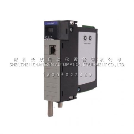
Picture a combined-cycle power plant’s turbine protection cabinet. Sixteen status bits have to reach the ControlLogix rack: breaker auxiliary contacts from the 125 V DC control bus, lube-oil pump relay feedback, emergency trip solenoid status from an independent UPS-fed circuit, and a handful of fire-gas panel contacts whose negative leg is tied to yet another ground. Under normal conditions those DC references sit a few volts apart. During a ground fault on one bus, the difference is no longer a few volts.A standard group-common 24 V DC input module would force all sixteen returns onto one reference. Circulating current, corrupted states, and the occasional “contact changed while nothing moved” phantom. That is the exact failure that never gets written up as a component fault — it gets written up as a nuisance trip, and the operations log blames the instrument technician.The 1756-IH16I changes the geometry. Each channel’s common is its own, so the three DC systems never share a return path inside the rack. The module becomes an insulating boundary between distribution boards, not a forced convergence point. The result is boring, which is the highest compliment a protection panel can earn: the inputs read what the contacts say, the backplane stays clean, and the only thing that changes during a ground-event is the one channel that was actually supposed to change.
Parameter
| Main Parameters | Value / Description |
|---|---|
| Product Model | 1756-IH16I |
| Manufacturer | Allen-Bradley, Rockwell Automation (ControlLogix platform) |
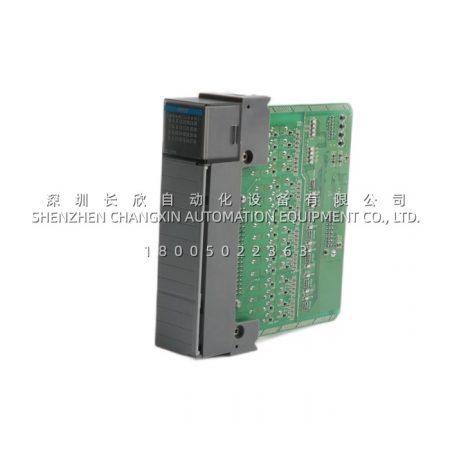
| Product Category | 16-point discrete DC digital input module, individually isolated |
| Voltage family | 125 V DC sink/source — the “H” suffix denotes the 125 V DC family, not 24 V DC |
| Operating voltage range | 90 … 146 V DC — comfortably covers battery float conditions that sit well above or below nominal 125 V |
| Nominal input voltage | 125 V DC |
| Number of inputs | 16, individually isolated (point-to-point isolation, not group-common) |
| Isolation rating | 250 V continuous between inputs; input-to-backplane barrier to the same class. This is the number that lets you mix DC distributions in one module |
| On-state current | 1 mA @ 90 V DC, rising to ~3 mA @ 146 V DC — very light loading on relay contacts and breaker auxiliaries |
| Off-state voltage, max | 20 V DC (threshold below which the channel reliably reports OFF) |
| Off-state leakage, max | 0.8 mA |
| Input delay, Off→On | 2 ms max hardware delay + selectable filter (0 / 1 / 2 ms) |
| Input delay, On→Off | 6 ms max hardware delay + selectable filter (0 / 1 / 2 / 9 / 18 ms) |
| Filtering note | The long 18 ms On→Off setting is there for contact-chatter suppression on mechanical breakers; you pay in response time, so keep fast-changing signals on the short settings |
| Backplane current | 125 mA @ 5.1 V DC; 3 mA @ 24 V DC — roughly 0.71 W total, so chassis power budgeting is rarely the constraint |
| Power dissipation | 5 W max @ 60 °C (≈ 17 BTU/hr) |
| Terminal block | 36-pin RTB, not included — order 1756-TBNH (screw) or 1756-TBSH (spring clamp) separately; 1756-JMPR jumper bars for non-isolated daisy-chain wiring if you deliberately give up isolation on selected points |
| Wiring style | Sink or source configurable per channel by how you land the field common; each channel has its own GND-x return on the RTB |
| Communication format | Module-defined AB:1756_DI:I:0 (input-only listen data) or AB:1756_DI_Timestamped:I:0 for CST-timestamped input data |
| Diagnostics | 32-bit Fault word per module (low 16 bits meaningful): OpenWire, FieldPwrLoss, FuseBlown, NoLoad, OutputVerifyFault, CommFault. If the controller loses the connection, all points flag fault rather than reporting stale “good” data |
| Timestamping | CST (Coordinated System Time) timestamping available — every edge carries a millisecond-accurate label, which matters for trip-sequence reconstruction |
| Firmware | Major revision 2 (latest 2.002.x) and major revision 3 (latest 3.004); Rockwell’s rule is strict: a 3.x module cannot be flashed back to 2.x, and forcing it renders the module inoperable |
| Chassis fit | Any 1756 ControlLogix chassis (1756-A4, -A7, -A10, -A13, -A17 and the 1756-Ax local/remote variants); slot position is free, no backplane jumpers |
| Hot-swap behaviour | 1756 I/O is hot-swappable in practice; replace the card with the chassis powered, then re-establish the connection in Studio 5000 — but land the field wiring cold, because the RTB removal is what disconnects your 125 V DC returns |
| Environmental | 0 … +60 °C operating, −40 … +85 °C storage, 5–95 % RH non-condensing; pollution degree 2; UL 508, CE, C-Tick |
| Hazardous area | Not intrinsically safe, not ATEX/IECEx rated. Barrier or galvanic isolator required before this module sees a Zone 1/2 field circuit |
| Lifecycle | Active per Rockwell’s lifecycle listing; standard lead time is long enough that most plants hold one bench-verified spare rather than wait |
| Form factor | Single-slot 1756 profile, ≈ 0.2 kg module-only, standard 1756 depth behind the rail |
Read the catalog number like a code, because it is one. 1756-I = ControlLogix discrete input. The H = 125 V DC (IA is 120 V AC, IB is 24 V DC, IM is 240 V AC, IC is 48 V DC, IG is 5 V TTL). The 16 = sixteen points. The trailing I = individually isolated. So 1756-IH16I is not “a 24 V DC card with a different label” — fitting a 1756-IB16I in its place will wire correctly and then misread every contact on a 125 V DC bus.
Technical Principles and Innovative Values
Innovation Point 1 — Isolation is per channel, not per group, and that is the whole product. Most DC input modules group eight or sixteen commons together behind one barrier. Cheap, dense, and fine until two field devices disagree about where zero volts lives. The 1756-IH16I puts an independent galvanic barrier on every channel, then gives each its own GND-x terminal on the RTB. You can wire channel 0 as a sinking input from Distribution Board A, channel 1 as a sourcing input from an isolated UPS feeder, and channel 15 from a third ground domain — and none of the three can pump current through the others. No external relay bank, no signal conditioner, no “we’ll just tie the negatives together and see.”Innovation Point 2 — The 90–146 V DC window is engineering margin, not a datasheet vanity. Real 125 V DC systems are battery-backed and they float. A healthy float can sit at 135 V, and a large motor starting downstream can pull the bus under 100 V before the charger recovers. The 1756-IH16I accepts the entire band. That means a retrofit project does not turn into a panel redesign just because the site’s DC board runs high, and it means the module does not creep out of spec during the twenty seconds after a charger trip. The 1 mA on-state current at the low end is gentle enough that a weary breaker auxiliary contact still pulls the input high without welding its way through contact resistance.Innovation Point 3 — Filter settings you can tune to the device instead of to the panel. Off→On is 2 ms hardware plus 0/1/2 ms of filter; On→Off is 6 ms plus 0/1/2/9/18 ms. That asymmetric On→Off tail is deliberate: mechanical breaker and relay contacts bounce on make and chatter on break, and the break-side chatter is what generates the nuisance transition. A vibrating screen, a big contactor, or a trip solenoid that rings for half a cycle gets the 18 ms filter on that one channel while the clean solid-state feedback next to it stays at 0 ms. You are tuning response versus cleanliness per point, not globally. In a turbine trip chain, that decision is documented and defensible during a functional-safety review.Innovation Point 4 — CST timestamps turn a flaky contact into a forensic record. Pair the 1756-IH16I with a ControlLogix controller running Coordinated System Time and select the timestamped communication format. Every input edge gets a millisecond-accurate time label. When the question is “which breaker opened first, and was it before the lube-oil pressure dropped,” you no longer argue from the operator’s video feed. You open the trend. For trip-sequence analysis, incident investigation, and the “prove the interlock fired in the right order” paperwork, this is the difference between a narrative and evidence.Innovation Point 5 — The fault word fails loud instead of failing quiet. The module’s 32-bit Fault member maps OpenWire, FieldPwrLoss, FuseBlown, NoLoad, OutputVerifyFault and CommFault as individual bits. Critically, a lost connection to the controller marks all points faulted rather than letting them hold their last value. That is a deliberate design choice: a stale “breaker closed” bit during a comms outage is dangerous, a flagged fault is merely inconvenient. The 1756-IH16I chooses the inconvenient path, which is why it belongs in protection-adjacent panels.

Reviews
There are no reviews yet.