
Technical Specifications
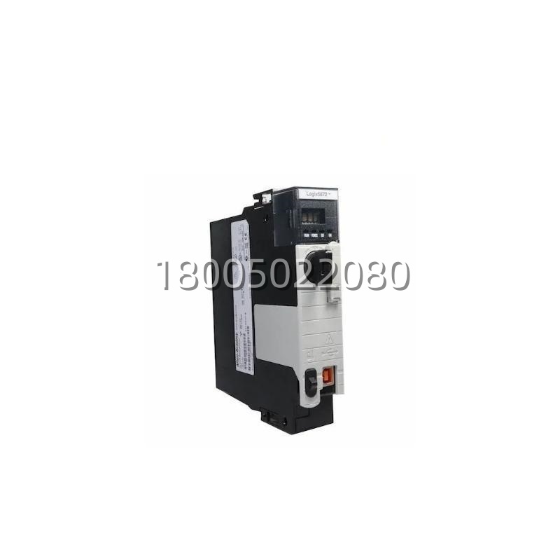
Product Model | 1756-L71Manufacturer | Rockwell Automation / Allen-BradleyProduct Type | ControlLogix 5570 Series Programmable Automation Controller (PAC)Controller Name | Logix5571User Memory | 2 MB (non-volatile with energy storage module)I/O Capacity | 128,000 digital points / 4,000 analog points (distributed via networked I/O)Motion Control Axes | Up to 100 axes (EtherNet/IP or SERCOS II interface modules required)Maximum Tasks | 32 (any mix of continuous & periodic); max 100 programs per taskLocal I/O (backplane) | Up to 128 modules in local chassis (limited by power budget & slot count)Front Ports | 1 × USB 2.0 (for PC programming via RSLinx Classic / Studio 5000)Display | Front-panel 4-character alphanumeric LCD (status, fault codes, IP octets scroll)Energy Storage | Requires 1756-ESMCAP (supercapacitor module) for program retention during power lossBackplane Current Draw (5 V) | 1200 mA typicalBackplane Current Draw (24 V) | 5 mA (logic only; display adds negligible load)Operating Temperature | 0 °C to +60 °C (32 °F to 140 °F)Storage Temperature | -40 °C to +85 °CAgency Approvals | UL Listed, cULus, CE, C-Tick, FM (Class I Div 2 Groups A,B,C,D T4A)Required Software | Studio 5000 Logix Designer v18 or later (Logix5000)Chassis Compatibility | Any 1756 chassis (1756-A4, 1756-A7, 1756-A10, 1756-A13, 1756-A17)
Main Features and Advantages
The Allen-Bradley 1756-L71 brings several compelling advantages to the modern automation engineer. First among them is the elimination of the traditional lithium battery. Paired with the 1756-ESMCAP energy storage module, the controller retains all user programs and tag values for a minimum of 30 minutes after power loss—extendable by adding a second ESMCAP in a companion slot. This design removes the maintenance burden of scheduled battery swaps and eliminates the leading cause of unexpected program loss in legacy PLCs: a dead or leaking battery discovered too late. An LED on the ESMCAP indicates charge status, and Studio 5000 can alarm when capacitor health degrades.Multitasking capability sets the Allen-Bradley 1756-L71 apart from simpler PLCs. With support for 32 concurrent tasks—each schedulable as continuous (free-running) or periodic (down to 1 ms) with priority levels—engineers can partition machine sequencing, process loops, motion supervision, and communications handling into logically isolated programs. This improves scan-time predictability and makes large applications easier to document and maintain. Tag-based addressing (instead of fixed file/element notation) provides symbolic naming, data typing, and structure—features that accelerate development and reduce addressing errors.Integrated motion is native to the Logix engine in the Allen-Bradley 1756-L71: no separate motion card is required for basic coordination; simply add a Kinetix® servo drive on EtherNet/IP or a SERCOS interface module and the same controller handles axis definition, camming, gearing, and homing routines. The front-panel LCD is another practical benefit—technicians can scroll through controller state (RUN / PROGRAM / FAULT), view the last fault code in hexadecimal, or check IP address segments directly at the rack, which dramatically reduces mean-time-to-diagnose in the field.Remove-and-Insert-Under-Power (RIUP) is supported: the Allen-Bradley 1756-L71 can be swapped in a running chassis (with the exception that the controller itself cannot be removed while executing logic it hosts) and will reload its project from non-volatile memory upon reinsertion. Combined with the extensive Rockwell knowledge base and global spares availability, the Allen-Bradley 1756-L71 represents a low-risk, high-capability choice for sustaining and upgrading ControlLogix-based process and discrete control systems.
Application Field
The Allen-Bradley 1756-L71 is deployed across a broad spectrum of industries where a single controller must manage substantial I/O counts, multiple communication networks, and sometimes coordinated motion. In automotive final assembly and body shops, the Allen-Bradley 1756-L71 orchestrates conveyor zones, weld-gun sequencing, and RFID-tracked build variations—often communicating with upstream cell controllers via EtherNet/IP and interfacing to remote 1734 POINT I/O or 1794 FLEX I/O drops on the shop floor. Its 2 MB memory is ample for the logic, array-based part-tracking, and HMI faceplate data required in these environments.In process industries—oil & gas gathering stations, chemical batch blending, water/wastewater treatment—the Allen-Bradley 1756-L71 runs continuous PID loops, manages alarm/event logging to a PlantPAx® system, and serves as the gateway between fieldbus-connected instruments and a site-wide DCS or SCADA host. The ability to mix 1756 analog I/O, HART-enabled modules, and safety I/O (GuardLogix companion) in the same chassis simplifies panel design and reduces component count. Packaging machinery OEMs specify the Allen-Bradley 1756-L71 when their equipment exceeds the I/O or motion axis limits of CompactLogix™, needing the modular backplane expansion and redundancy options only ControlLogix can provide.For companies migrating from obsolete PLC-5 or SLC 500 systems, the Allen-Bradley 1756-L71 offers a direct evolutionary path: import tools in Studio 5000 convert legacy ladder files where possible, and the familiar Rockwell tag-structure and troubleshooting paradigms shorten the learning curve for existing maintenance teams. Whether the requirement is high-speed packaging, batch process control, or a hybrid discrete/process cell, the Allen-Bradley 1756-L71 delivers the computational headroom and I/O scalability to meet today’s demands with room for tomorrow’s expansion.
Related Products
- 1756-L73 — ControlLogix 5570 controller with 8 MB user memory; higher-capacity alternative to the 1756-L71 for larger programs or more motion axes.
- 1756-L75 — ControlLogix 5570 controller with 16 MB or 32 MB memory; top-tier model for very large or redundant systems.
- 1756-ESMCAP — Energy storage capacitor module (supercap) required by the 1756-L71 to retain program/data during power loss; replaces traditional battery.
- 1756-PA72 / 1756-PB72 — 120/230 V AC or 24 V DC power supply modules for ControlLogix chassis hosting the 1756-L71.
- 1756-A7 / 1756-A10 — ControlLogix chassis (7-slot / 10-slot) that physically houses the 1756-L71, power supply, and I/O/communication modules.
- 1756-EN2T / 1756-EN3T — EtherNet/IP communication modules providing network connectivity for the 1756-L71 (which has no onboard Ethernet port).
- 1756-L7SP — GuardLogix 5570 safety partner CPU; used with a standard 1756-L7x (including 1756-L71) in a safety-rated CIP Safety system.
- Studio 5000 Logix Designer — Engineering software required to develop, download, and maintain applications on the 1756-L71.
- 1784-USBCAB — USB programming cable for direct PC-to-controller connection via the front USB port of the 1756-L71.
Installation and Maintenance
Pre-installation preparation: Before installing the 1756-L71, select an appropriate 1756 chassis size (A4/A7/A10/A13/A17) and verify that the chosen 1756 power supply (PA72, PB72, etc.) can support the backplane current draw of the controller plus all planned modules—the 1756-L71 draws approximately 1200 mA at 5 V DC. Install the power supply in the leftmost slot (Slot 0) and the 1756-L71 in any subsequent slot (commonly Slot 1 for clarity). Ensure the 1756-ESMCAP energy storage module is installed in an adjacent spare slot and its LED shows green (charged). Connect a programming PC via USB cable to the front port or via Ethernet through a 1756-ENxT module once IP is assigned. In Studio 5000 Logix Designer, create or open a project selecting “1756-L71” as the controller type, set the slot number to match physical placement, and download the application. Verify chassis ground continuity and confirm the controller transitions to RUN mode without faults.Maintenance recommendations: The 1756-L71 is largely maintenance-free thanks to the battery-less design. Periodically check the 1756-ESMCAP status LED—if it flashes red, the supercap may be failing or not receiving sufficient charge time after power-up (allow minimum 4 hours for full charge). Inspect the chassis backplane for dust accumulation and ensure module ejector levers are fully seated. If the controller enters a faulted state, read the hex code on the front LCD or connect via Studio 5000 to view the Major/Minor fault detail—common causes include watchdog timer expiration, I/O module mismatch (electronic keying), or array subscript overflow. Firmware should be kept consistent with your Studio 5000 version matrix; use ControlFLASH to update. For spare-holding purposes, keep a configured 1756-L71 with matching firmware revision and a copy of the application on removable media (USB stick via front port or archived .ACD file) to enable rapid swap in the event of a hardware failure.

Reviews
There are no reviews yet.