
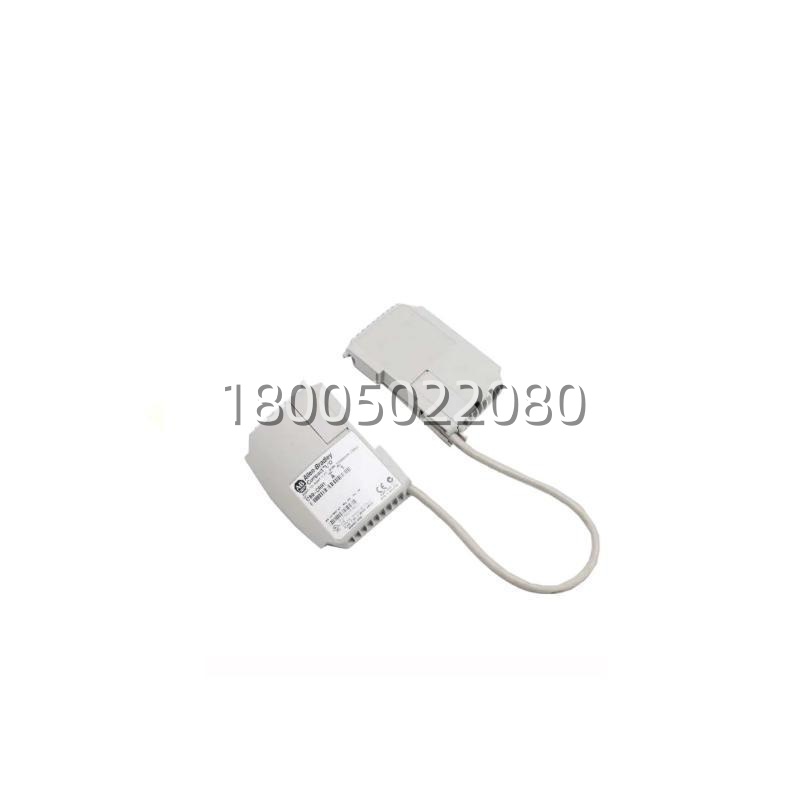
Technical Specifications
| Parameter | Value |
|---|---|
| Product Model | 1769-CLL3 |
| Manufacturer | Allen-Bradley (Rockwell Automation) |
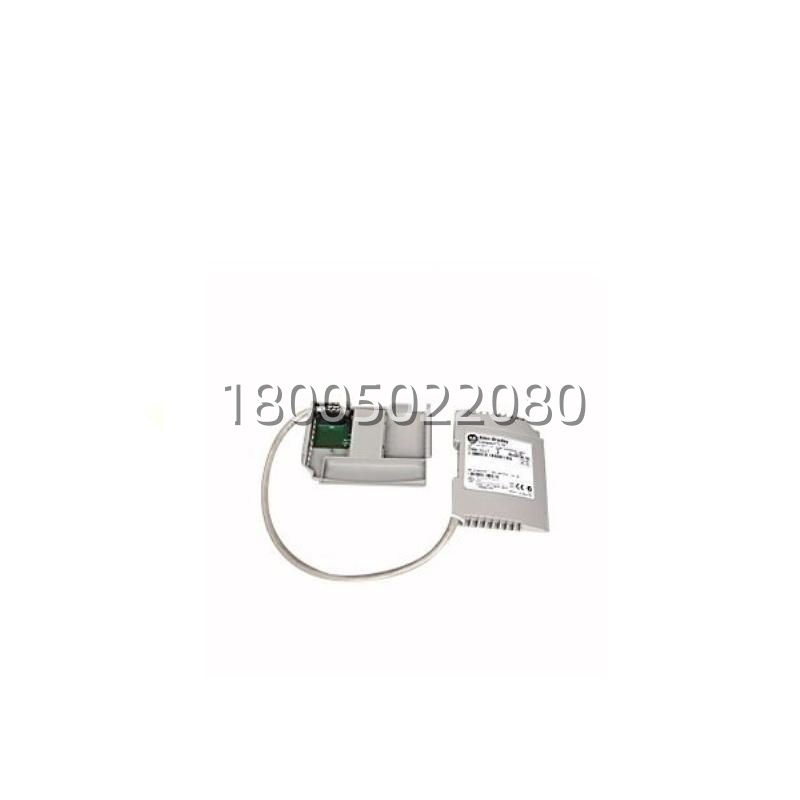
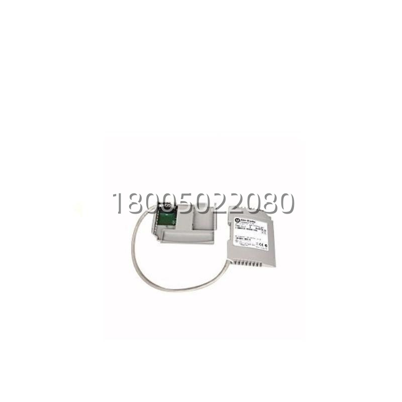
| Product Type | 1769 Compact I/O / CompactLogix Bus Expansion Cable (Left-to-Left) |
| Cable Length | 1 m (3.28 ft) |
| Short-Sku Sibling | 1769-CLL1 = 305 mm (1 ft) |
| Approx. Weight | 350 g (0.77 lb) |
| Compatible Platforms | CompactLogix 5370 L2/L3, 1768 CompactLogix, 1769 Compact I/O banks |
| Max Cables per System | 2 (allowing up to 3 I/O banks total) |
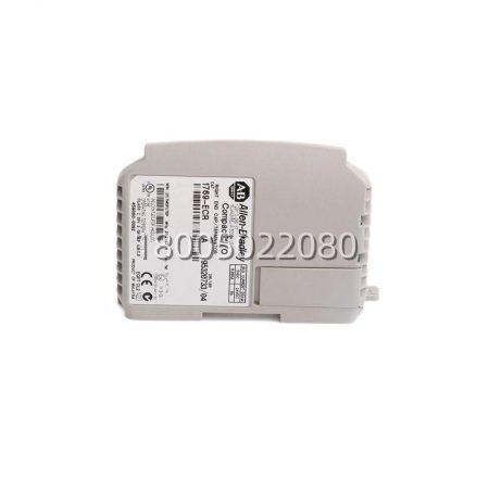
| Bank Requirement | Each bank must have its own 1769 power supply; last bank requires 1769-ECR |
| Operating Temp | 0 °C to 60 °C (32 °F to 140 °F) |
| Certifications | c-UL (CSA C22.2 No. 142), UL 508, Class I Div 2 A/B/C/D, CE, C-Tick |
| Mounting Context | Plugs between left face of Bank A and left face of Bank B in 1769 tongue-in-groove rack |
Main Features and Advantages
Enables True Multi-Bank 1769 ScalingThe core value of the 1769-CLL3 is architectural: a bare 1769 processor + power supply + I/O string hits a wall at roughly 8–16 modules depending on power budget. By inserting the 1769-CLL3 between banks, engineers split the I/O across two (or three, with a second cable) independent power-supply domains while the CompactLogix processor still sees all modules on one backplane. This is especially valuable on 1769-PB2/PA2 supplies where 5V and 24V budgets fill up quickly with mixed analog + high-channel-count digital loads. The 1769-CLL3 keeps the addressing flat—no remote adapter, no devicenet bridge, no extra node—just more I/O on the same processor.1 m Reach for Panel-Layout FlexibilityThe “3” in 1769-CLL3 denotes 1 meter, versus the “1” (1769-CLL1) at 305 mm. In real panels, this matters: high-density I/O for a packaging line might be split across a 800 mm cabinet width, or a 1769 rack might be partitioned either side of a 24V DC hydraulic-power duct. The 1769-CLL3 spans that gap without custom wiring or external terminal-cabinet transitions. Signal integrity on the 1769 backplane ribbon is preserved through Rockwell’s molded tongue connectors, so timing and noise margins stay within CompactLogix spec even at the full 1 m.Tool-Free Plug-In With 1769 Tongue MechanicsLike all 1769 accessories, the 1769-CLL3 uses the same tongue-and-groove + release-pin mechanic as the I/O modules themselves. No screws, no crimping, no pin-alignment jig—slide the cable’s left-face connector onto the rightmost module of Bank A, route the 1 m loom, and tongue the right-face connector into the leftmost module of Bank B. The 1769-CLL3 clicks home the same way a 1769-IQ32 clicks next to a 1769-OB16. This keeps panel-build labor predictable and eliminates wiring errors that plague hand-made backplane jumpers.Full Safety & Hazardous-Area Certification AlignmentBecause the 1769-CLL3 passes the same backplane signals that carry I/O data in Class I Div 2 installations, Rockwell certifies it to the same envelope as the 1769 modules: c-UL, UL 508, CE, C-Tick, and Class I Div 2 Groups A–D. Specifying the 1769-CLL3 in oil & gas, chemical-batch, or grain-handling panels doesn’t break the hazardous-area paperwork—the cable is a listed component of the 1769 system, not a field-modified jumper.Sibling Variant Clarity (Avoiding Misorders)The 1769 expansion family has six SKUs—CLL1/CLL3 (left-to-left), CRR1/CRR3 (right-to-right), CRL1/CRL3 (right-to-left)—and ordering the wrong direction is a classic panel-build mistake. The 1769-CLL3 is specifically “Bank A left face → Bank B left face,” used when two banks sit side-by-side but the processor faces the same direction for both. If the panel layout instead stacks Bank B off the rightface of Bank A, the correct SKU would be 1769-CRR3. Calling this out in the feature section prevents the “cable arrived, doesn’t reach the orientation” return scenario that costs commissioning days.
Application Field
The 1769-CLL3 is specified whenever a CompactLogix-controlled machine or process exceeds the I/O density or power budget of a single 1769 bank and the designer chooses to stay on one processor rather than step up to a larger Logix platform. In mid-size packaging lines—form-fill-seal, case packer, palletizer cells—the main headframe I/O (servo drives, registration sensors, heater zones) might consume 10+ modules on Bank A with a 1769-PA2 supply, while the downstream conveyor zone (diverter solenoids, barcode scanners, reject gates) needs another 6–8 modules that would push Bank A over its 5V/24V budget. A 1769-CLL3 inserts between the two, Bank B gets its own 1769-PB2, and the CompactLogix 5370 L3 processor addresses all ~20 modules transparently. The 1 m length lets the panel builder physically separate the 240V AC power section (Bank A) from the 24V DC conveyor section (Bank B) across a cabinet divider while keeping one processor.In material-handling ASRS sub-cells and automotive body-shop sub-assemblies, the 1769-CLL3 appears where 1769 I/O is split across a moving carriage and a fixed mast—here the 1 m cable loom is sometimes dressed in drag-chain alongside 24V field harnesses, though Rockwell doesn’t rate CLLx explicitly for continuous flex, so static-separate layouts are the norm. In batch-process skids (pharma, food & beverage CIP, chemical blending), the 1769-CLL3 lets the skid-mounted Bank A (valve manifolds, flow meters, RTDs) talk to a cabinet-mounted Bank B (HMI local I/O, VFD keypad interfacing) with one CompactLogix L30ER or L33ER processor spanning both. For MRO sustainment on 2005–2018 vintage CompactLogix installs, the 1769-CLL3 is a frequent “oh-we-need-another-bank” add-on: original panel was 8 modules, production added a vision station + reject lane + wash-zone I/O, and rather than migrate to a ControlLogix chassis, the maintainer drops a 1769-CLL3 + second 1769-PA2 + 6 more modules and keeps the original RSLogix 5000 / Studio 5000 project largely intact.One edge case worth naming: the 1769-L23x controllers (the “all-in-one” CompactLogix with built-in I/O) ship with a right-end cap already fitted, so the 1769-CLL3 would attach to the leftof that controller if a left-bank expansion is needed, with the right side already capped—this trips up first-time L23x expanders who assume they need to buy an ECR (they don’t, on the L23x right side). The 1769-CLL3 fits that left-side e[x]pansion the same as on any 1769 bank.

Reviews
There are no reviews yet.