
Application Scenarios:
In a chemical processing plant’s pump station, multiple pumps transfer corrosive fluids between tanks. Safe and reliable monitoring of pump status is critical. The FOXBORO FBMSSW module is installed in a field-mounted enclosure near the pumps. Sixteen field devices are wired to it: the running status contacts from each motor starter (8 pumps), high-level and low-level switch contacts from the suction and discharge tanks (6 points), and local emergency stop push buttons (2 points). The FBMSSW continuously scans these 16 dry contacts. When a pump starts, its motor starter auxiliary contact closes, and the corresponding channel on the FBMSSW detects the 24V DC loop closure, sending a “PUMP RUNNING” status to the control system’s controllers (e.g., a CP60). If a tank reaches a high level, the level switch contact closes, and the FBMSSW sends a “HIGH LEVEL ALARM” signal. This allows the DCS to display real-time status, log events, and execute interlock logic, such as preventing a pump from starting if the suction tank is empty.
Technical Principles and Innovative Values:
The FOXBORO FBMSSW serves as a robust and reliable bridge between simple field switch contacts and the sophisticated digital control system, emphasizing signal integrity and diagnostics.
Innovation Point 1: High-Density, Group-Isolated Design. The module efficiently consolidates 16 discrete signals into a single, compact unit, reducing panel space and wiring complexity. The channels are typically isolated in groups (e.g., 8 points per common), which provides a good balance between cost and noise immunity. This design prevents ground loops and mitigates the impact of electrical interference from one field device affecting others in a different group, ensuring signal accuracy in electrically noisy industrial environments.
Innovation Point 2: Dry Contact Versatility and Simplicity. The FBMSSW is designed for the most common and straightforward field device: the dry contact. It does not supply power itself but senses the presence of an externally supplied “wetting” voltage (e.g., 24V DC) when the contact closes. This simplicity makes it universally compatible with a vast array of field switches, relay contacts, and other two-wire devices without concern for sourcing vs. sinking conflicts, simplifying field wiring and device selection.
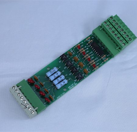
Innovation Point 3: Integrated Diagnostics and Visual Status. Each of the 16 channels features a dedicated LED that illuminates when the corresponding input is in the “ON” (contact closed) state. This provides immediate, at-a-glance diagnostics for technicians troubleshooting in the field, allowing them to quickly verify the state of limit switches, push buttons, or relay contacts without needing a laptop or accessing the control room graphics.
Application Cases and Industry Value:
Case Study: Centralizing Tank Farm Monitoring and Interlocks.
A large oil terminal had a tank farm with dozens of storage tanks. Each tank was equipped with local level switches (high, high-high, low) and block valve limit switches (open/close). Previously, status signals were wired individually over long distances to a central relay panel, leading to high installation costs and difficult troubleshooting. The terminal upgraded to a Foxboro I/A Series DCS using distributed I/O. FOXBORO FBMSSW modules were installed in junction boxes near groups of 4-5 tanks.
All local switch contacts from the nearby tanks were wired directly to these nearby FBMSSW modules over very short distances. The FBMSSW modules then communicated digitally to the control system over a single fieldbus cable. This dramatically reduced wiring costs and complexity. Operators in the control room now had real-time visibility of every tank’s level status and valve position. More importantly, safety interlocks were implemented in the controller: the FBMSSW’s signal indicating a “Tank High-High Level” could now directly and reliably interlock to close the tank’s inlet valve via a digital output module. The project engineer stated, “Distributing the FBMSSW modules in the field was a game-changer. We cut miles of cable, installation time, and future maintenance headaches. The per-channel LEDs alone have saved countless hours during commissioning and troubleshooting.”
Related Product Combination Solutions:
FOXBORO FBM201 / FBM202: Fieldbus Interface Modules. These are the communication heads to which the FBMSSW (and other FBMs) connect via ribbon cable. The FIM201/FIM202 provides the link to the Foxboro control network (e.g., over an I/A Series fieldbus).
FOXBORO CP60 / CP270: Control Processors. The brains of the I/A Series system that execute control logic based on the input statuses provided by the FBMSSW modules.
FOXBORO FBMSO / FBMSS: Digital Output Modules. Complementary modules that receive commands from the controller and switch field loads (e.g., motor starters, solenoid valves), often activated based on logic using FBMSSW inputs.
FOXBORO FBMCF / FBMCW: Foundation Fieldbus Modules. For analog I/O, showing the system’s modularity where the FBMSSW handles the discrete side.
FOXBORO PSS Power Supply System: Provides the conditioned and often redundant 24V DC power required for the field devices connected to the FBMSSW and for the module’s electronics.
FOXBORO AW51F: Workstation Software. The engineering and operator station environment where the points from the FBMSSW are configured, displayed on graphics, and used in control strategies.
External 24V DC Power Supply / IS Barrier: For use in hazardous areas, an intrinsic safety barrier or isolated power supply is placed between the field switches and the FBMSSW to provide the wetting voltage safely.
Installation, Maintenance, and Full-Cycle Support:
Installation involves mounting the FOXBORO FBMSSW module on a DIN rail within a Fieldbus Module assembly, which already contains the required Fieldbus Interface Module (FIM). The ribbon cable from the FBMSSW plugs into the FIM. Field wiring is connected to the terminal block of the FBMSSW: one side to the field switch contact, and the other side to the external wetting voltage source (e.g., 24V DC+). The common terminals for each isolation group must be connected to the return of the wetting voltage supply. Configuration is done in the Foxboro I/A Series control software, where each of the 16 points is given a tag name and associated with the correct hardware channel.
Maintenance is straightforward. The per-channel LEDs are the primary diagnostic tool. If a field device is actuated but the corresponding LED does not illuminate, technicians can check for field power, contact health, and wiring continuity. The module is designed for easy replacement if needed. Our full-cycle support ensures your discrete monitoring is robust and reliable. We provide detailed wiring diagrams, assist with point configuration in the Foxboro environment, and supply genuine, factory-tested modules and spare parts. We are committed to supporting the long-term health of your Foxboro I/A Series system.
Contact us for a customized solution to reliably integrate your field switch and contact signals into your Foxboro I/A Series DCS.


Reviews
There are no reviews yet.