Description:
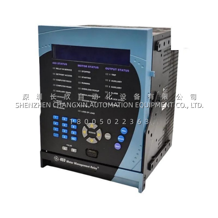
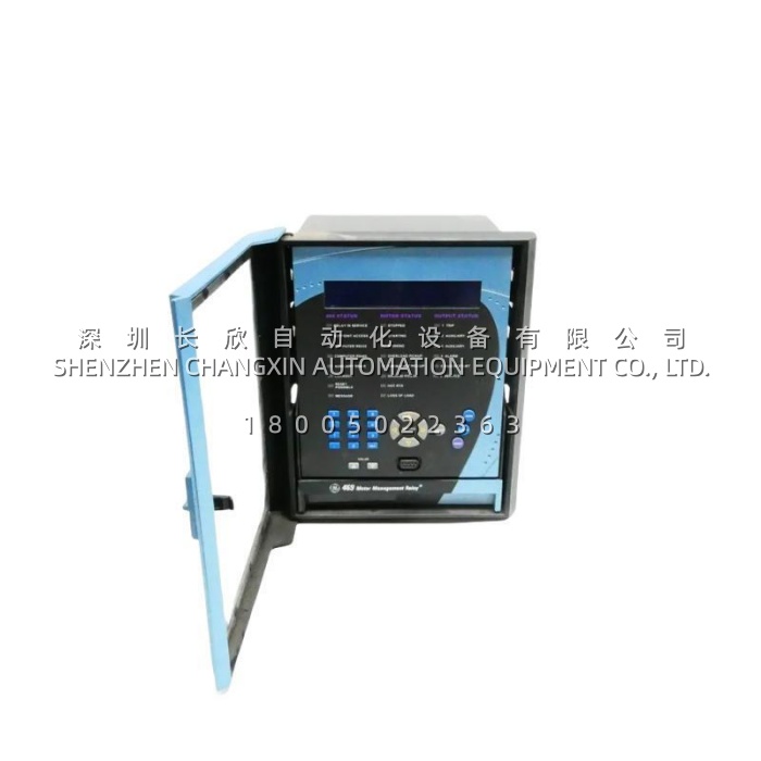
The 469-P5-HI-A20-E-H is a microprocessor-based motor management relay from GE Multilin (now GE Vernova Grid Solutions), part of the Multilin 469 / SR469 family of motor protection systems. It is built to protect, control, meter and diagnose medium and large horsepower three-phase motors and the equipment they drive, and it ships in the industry-standard SR-series draw-out arrangement — a removable relay unit mated to a fixed case that retains the field wiring and provides automatic CT shorting.Reading the order code tells you exactly what you are buying: 469 is the base platform, P5 specifies 5 A phase CT secondaries, HI is the wide-range control power supply (90–300 V DC / 70–265 V AC, 48–62 Hz), A20 provides four isolated 4–20 mA analog outputs, E is the enhanced front panel with the larger 40-character LCD, and H adds conformal coating for chemically corrosive or humid environments. Because the 469-P5-HI-A20-E-H carries protection, metering, control and diagnostics in one device, it replaces what would otherwise be a thermal overload relay, an RTD scanner, a transducer, a meter and an event recorder.One caveat worth stating plainly: GE has discontinued manufacturing of the 469 and recommends the Multilin 869 (or 859) as the forward alternative. That makes verified stock of the 469-P5-HI-A20-E-H genuinely strategic — it is the difference between a same-week board swap and a forced migration project. Note also that channel listings differ slightly on whether the “-E” suffix alone brings Ethernet; in the standard 469 order code, E denotes the enhanced display while Ethernet (10Base-T, Modbus TCP/IP) is a separate option. Check the nameplate before assuming network capability.
Application Scenarios:
Consider a refinery cooling water pump house with six medium-voltage pumps, each several hundred kilowatts. The pumps run continuously, the environment is humid and mildly corrosive, and a single pump loss forces a unit to cut throughput. Under the old electromechanical protection, the motors burned out quietly: a partially blocked impeller pushed the winding temperature up over weeks, the overload relay never saw it because the current stayed just below pickup, and the failure showed up as a ground fault at 2 a.m. Fitting the 469-P5-HI-A20-E-H changes that picture, because the relay’s thermal model is biased by real RTD feedback from the stator — it sees the hot spot that the current alone does not reveal, and it trips on temperature before the insulation fails.The second scenario is a mine crusher. A jammed crusher is a race between the motor’s thermal limit and the operator’s reaction time. The 469-P5-HI-A20-E-H detects the mechanical jam and stall condition directly, applies the learned motor starting and stall parameters, and trips the breaker in milliseconds rather than letting the operator “try it once more.” Here the value is not measurement — it is saving a rewinding several hundred thousand dollars.In both cases the pain point addressed by the 469-P5-HI-A20-E-H is invisible degradation. Motors rarely die from a single dramatic fault; they die from accumulated thermal stress, unbalanced supply, repeated starts and blocked cooling. This relay is designed to see all four, which is why it is found on boiler feed pumps, forced and induced draft fans, compressors, conveyor drives and large centrifugal pumps wherever unplanned motor failure is expensive.
Parameter:
| Main Parameters | Value / Description |
|---|---|
| Product Model | 469-P5-HI-A20-E-H (Multilin 469 / SR469 series) |
| Manufacturer | GE Multilin — GE Vernova Grid Solutions |
| Product Category | Motor management relay / digital motor protection system (draw-out) |
| Order Code Meaning | 469 base; P5 = 5 A phase CT secondary; HI = 90–300 V DC / 70–265 V AC control power; A20 = four 4–20 mA analog outputs; E = enhanced display; H = harsh-environment conformal coating |
| Control Power | 90–300 V DC or 70–265 V AC, 48–62 Hz — one part number covers virtually any station battery or AC control scheme worldwide |
| Current Inputs | Phase CT 5 A secondary (1 A variant available as P1); ground CT 1 A / 5 A or 50:0.025 sensitive CT detecting earth leakage down to 0.25 A; dedicated differential CT input for single-CT stator differential protection |
| Voltage Inputs | VT inputs configurable delta or wye — enables voltage-dependent overload curves, under/overvoltage, underfrequency and power elements |
| RTD Inputs | 12 individually field-programmable inputs; 3-wire 100 Ω platinum, 100/120 Ω nickel, 10 Ω copper — covers stator windings, bearings and ambient |
| Protection Functions | Thermal overload (15 standard curves plus custom and voltage-dependent), RTD and negative-sequence biasing, mechanical jam, stall/acceleration, starts-per-hour and time-between-starts, short circuit, phase and ground overcurrent, current unbalance, under/overvoltage, underfrequency, undercurrent, stator differential, broken rotor bar, dual overload curves for two-speed motors |
| Output Relays | 6 Form-C electromechanical relays, silver alloy contacts, 10 ms operate time, 10 A continuous make/carry — configurable for trip, alarm, auxiliary, block start and service |
| Analog Outputs | Four isolated 4–20 mA channels (A20) — typically mapped to current, thermal capacity used, hottest RTD and load for the DCS |
| Communication | Front RS232 (local programming), two rear RS485 (Modbus RTU); optional 10Base-T Ethernet (Modbus TCP/IP), RS422 and DeviceNet depending on build |
| Monitoring and Diagnostics | Full metering (A, V, W, var, VA, PF, Hz, Wh, varh, demand, torque, temperature), event recorder, oscillography, data logger trending, pre-trip data, learned motor parameters, self-test |
| Software | EnerVista 469 Setup, including the Motor Settings Auto-Configurator |
| Environment | −40 °C to +60 °C operating, −40 °C to +80 °C storage; up to 95 % non-condensing humidity; conformal coating (H) for corrosive or humid locations |
| Construction and Approx. Size | Draw-out unit in fixed SR-series case with automatic CT shorting; approx. 21.8 × 22.8 × 25 cm and approx. 7.3 kg with case; panel mount, IP40 front; UL, CSA, CE |
Technical Principles and Innovative Values:
- Innovation Point 1 — A thermal model that is corrected by reality, not just by current: Most overload protection estimates winding temperature from current alone. The 469-P5-HI-A20-E-H runs a full thermal model with six elements — overload curve, unbalance biasing, hot/cold safe stall ratio, cooling time constants, start inhibit and RTD biasing — and updates its thermal capacity used register every 0.1 second. Because RTD feedback and negative-sequence current both bias the model, a motor with blocked cooling or a supply imbalance is protected correctly, while a healthy motor is not nuisance-tripped.
- Innovation Point 2 — Voltage-dependent overload curves for high-inertia starts: On large fans, flywheels and long conveyors, acceleration time can exceed the safe stall time even though nothing is wrong with the motor. The 469-P5-HI-A20-E-H dynamically adjusts its overload curve according to system voltage during acceleration, so a low-voltage start does not produce a false trip and a genuinely dangerous start still trips quickly. This is the kind of feature that only exists in a device built by people who commission real motors.
- Innovation Point 3 — Fifteen standard curves plus custom and voltage-dependent formats: Rather than forcing the motor to fit the relay, the 469-P5-HI-A20-E-H lets the engineer match the motor vendor’s published thermal limit curve, including separate curves for two-speed motors. That alignment is what allows a plant to run close to the motor’s true capability instead of backing off with a conservative safety margin that wastes capacity.
- Innovation Point 4 — Draw-out construction with automatic CT shorting: The relay unit pulls out of its fixed case while the case keeps the field wiring and automatically shorts the CT secondaries. In practice this means a suspected relay can be swapped in minutes without disturbing a single CT lead, and without an outage to re-terminate instrument transformers — a genuine reduction in both downtime and the risk of an open-circuited CT.
- Innovation Point 5 — Diagnostics that shorten the investigation, not just the trip: Event recorder, waveform capture (oscillography), data logger trending and pre-trip data stored inside the 469-P5-HI-A20-E-H mean the question “why did it trip” is answered from the relay itself rather than guessed at. Combined with built-in simulation functions for commissioning, this cuts both troubleshooting time and the cost of periodic testing.
- Innovation Point 6 — Conformal coating for the environments that actually kill electronics: The H suffix is not marketing. Moisture, salt air, hydrogen sulphide and dust are the dominant causes of premature relay failure in water, wastewater, mining and offshore service. The 469-P5-HI-A20-E-H is coated to survive exactly those atmospheres, which is why this particular suffix is disproportionately represented in harsh-service panels.