Description:
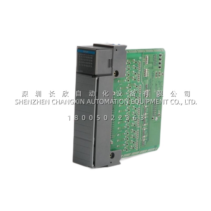
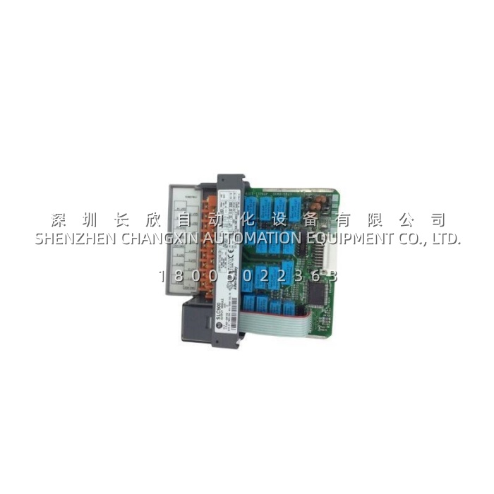
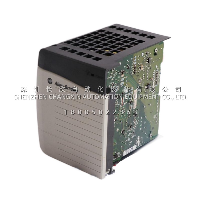
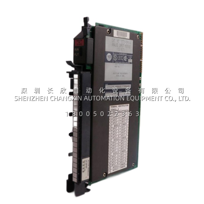
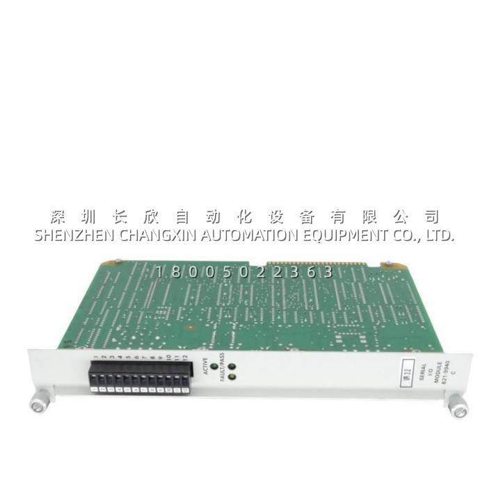
The 621-9940C is a Serial I/O Module (SIOM) from Honeywell for the IPC 620 / 621 programmable controller and I/O system. It is the node controller of a remote serial I/O card file: it collects data from the I/O modules sitting in its own rack and exchanges that data with the Serial Link Module in the processor card file over a serial channel.In practical terms, 621-9940C is what lets a Honeywell 620 Logic Controller place I/O hundreds of metres away from the processor and still treat it as part of the same machine. It sits in slot N of a full-size I/O rack or slot H of a half rack, and it is configured entirely in hardware — four 8-position and one 4-position DIP switch bank set the module’s absolute starting address, the fault response, and the I/O density of every slot in its card file. Note for anyone sourcing a replacement: the C suffix denotes CE conformity to the low-voltage and EMC directives; it does not denote hot-swap capability. Only the R suffix does that.
Application Scenarios:
A water treatment authority operates a filtration plant where the original design put the processor in a central control room and the I/O in six field cabinets spread across the site — chemical dosing, filter gallery, backwash pumps, sludge handling, inlet works and outlet monitoring. Re-homing all that I/O would mean re-pulling thousands of metres of cable through an operating plant, so the serial I/O architecture has to stay. The plant’s real problem is different: two of the six remote card files have been running for more than twenty-five years, the SIOMs are original, and there is no documentation of how the DIP switches were originally set.Dropping in 621-9940C as a like-for-like replacement solves the immediate failure, and the interesting part is how the configuration is recovered. Because the SIOM’s identity is defined by its DIP switches rather than by software, the starting address of each card file can be read straight off the switch banks of the old board — SW1 gives the absolute starting address, SW3 through SW5 give the I/O points per slot — and transferred to the new unit before it ever goes into the rack. There is no laptop, no configuration download and no risk of loading the wrong project.The second pressure in that plant was a recurring intermittent fault that had been blamed on the modules themselves. In a multidrop serial channel, terminating resistors are required at each extreme end to match cable impedance, and two are required in the last SIOM on the channel. Where an original installation used 200 Ω resistors and a later cabinet addition used 300 Ω — or where the resistor was simply never fitted in a moved cabinet — the channel runs with reflections that look exactly like a failing module. Establishing the termination correctly across the whole link removed a fault class the plant had been chasing with spare parts for years.This pattern — long-lived distributed serial I/O, hardware-defined addressing, and termination as the hidden variable — is why 621-9940C matters in water and wastewater, power generation auxiliaries, chemical and petrochemical plants, metals and mining conveyors, and any facility whose Honeywell 620-era distributed I/O is still doing useful work.
Parameter:
| Main Parameters | Value / Description |
|---|---|
| Product Model | 621-9940C (base model 621-9940, C = CE-compliant variant) |
| Manufacturer | Honeywell |
| Product Category | Serial I/O Module (SIOM) — serial I/O card file controller / remote I/O node interface |
| Host System | Honeywell IPC 620 / 621 I/O system, used with the 620 Logic Controller System (620-15, 620-25, 620-35) and in Honeywell DCS installations |
| Function | Collects data from the I/O modules in its serial I/O rack and interfaces with the Serial Link Module (SLM) in the processor card file |
| Slot Position | Slot N in a full-size I/O rack; slot H in an I/O half rack |
| I/O Density Configuration | Each I/O slot independently set to 0, 8, 16 or 32 points; total I/O must remain within the 620 Logic Controller’s I/O capacity |
| Addressing | Four 8-position DIP switch banks plus one 4-position bank. SW1 sets the absolute starting address from 0 to 2032 in increments of 8; SW2 sets rack output states on fault plus normal or test mode; SW3, SW4 and SW5 set the I/O points per card file slot |
| Serial Channel Requirements | Terminating resistors required at each extreme end of every serial channel to match cable impedance; 200 Ω or 300 Ω depending on installation; two resistors required in the last SIOM of a multidrop channel |
| Serial Cable | Belden 9729 or equivalent, per Honeywell specification |
| Interfaces With | 621-9939 Serial Link Module (SLM) in the processor card file; one or two SLMs in slots L and/or M, each controlling two serial I/O channels |
| Diagnostics & Status | Onboard LED status indication; fault and communication-fault response behaviour selected by DIP switch |
| Power Supply | Powered from the IPC 620 I/O rack power supply via the backplane; a standard rack supply supports up to 3 analog/serial modules, an extended supply up to 11 |
| Physical & Environmental | Approx. 264 × 32 × 127 mm, 0.61 kg; operating temperature 0 °C to +60 °C; CE conforming (LVD and EMC directives) |
| Suffix Convention | C = CE compliant. R = may be removed and inserted while the rack is powered. 621-9940C carries C only — it is not rated for insertion under power. The redundant-capable variant is 621-9938R / 621-9938RC |