Description:
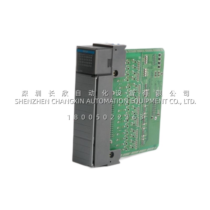
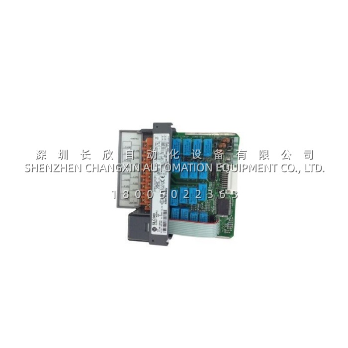
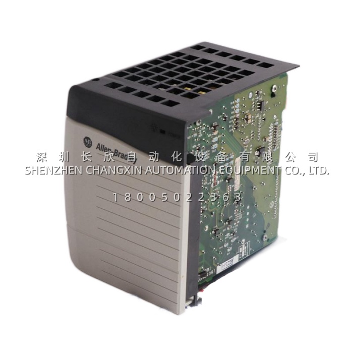
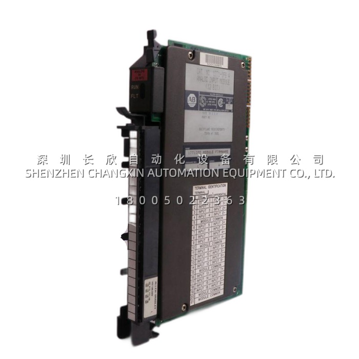
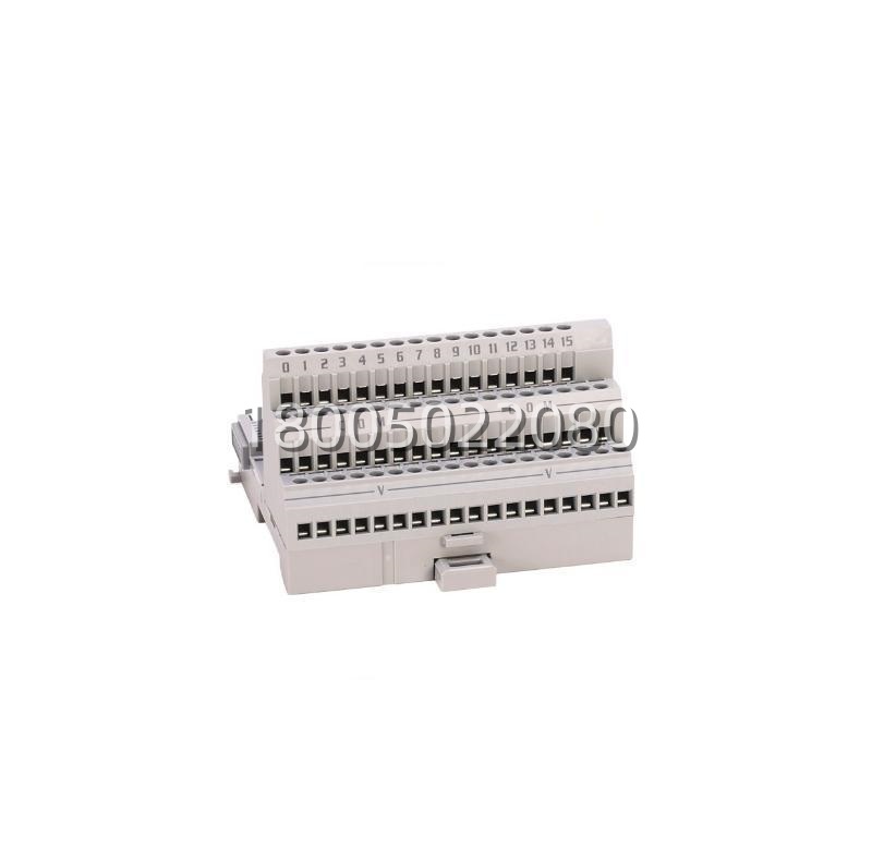
The 1794‑TB3 is a 3‑wire screw terminal base unit for Allen‑Bradley’s FLEX I/O distributed I/O system. It provides 16 I/O points with dedicated common and power terminals, supporting cage clamp (screw) connections for field wiring. Designed for 35mm DIN rail mounting, it acts as the interface between field devices (sensors, actuators) and plug‑in FLEX I/O modules (digital, analog, specialty). Its modular design allows hot‑swapping of I/O modules without disturbing field wiring.
Application Scenarios:
In a太原 automotive assembly line’s tooling station, multiple 1794‑TB3 bases are mounted in a control cabinet. Each base hosts a 1794‑IB16 input module connected to 16 proximity sensors. The TB3’s three‑row terminal layout (signal, common, +24V) simplifies wiring for PNP sensors, while its removable module feature allows technicians to replace a faulty input module in seconds without touching the field wiring, minimizing machine downtime.
Parameter:
| Main Parameters | Value / Description |
|---|---|
| Product Model | 1794‑TB3 |
| Manufacturer | Allen‑Bradley (Rockwell Automation) |
| Product Family | FLEX I/O Terminal Base Units |
| Terminal Type | 3‑Wire Screw Clamp (Cage Clamp) |
| I/O Points | 16 (Terminals 0–15) |
| Common Terminals | 18 (Terminals 16–33, internally connected) |
| +V Power Terminals | 18 (Terminals 34–51, internally connected) |
| Voltage Rating | 125V AC/DC (Continuous) |
| Current Rating | 10A Max (Per Terminal, limited by module) |
| Wire Range | 0.34 – 3.3 mm² (22 – 12 AWG) |
| Screw Torque | 0.56 – 0.79 N·m |
| Mounting | 35 mm DIN Rail or Panel Mount |
| Backplane Power | 5V DC @ 640 mA (FLEXBus) |
| Operating Temperature | 0 °C to +55 °C (Standard); -20 °C to +70 °C (Extended) |
| Enclosure Rating | IP20 (Open‑Style, for Cabinet Use) |
| Dimensions (WxHxD) | Approx. 94 x 94 x 69 mm |
| Weight | Approx. 0.26 kg |
Technical Principles and Innovative Values:
- Innovation Point 1: Three‑Row Terminal Layout for Clear Wiring Separation. Unlike generic terminal blocks, the 1794‑TB3 segregates terminals into three distinct rows: Row A (I/O signals 0–15), Row B (Common/COM), and Row C (+V Power). This physical separation prevents wiring errors (e.g., accidentally shorting 24V to a signal line) and streamlines the connection of 3‑wire field devices like PNP sensors and powered actuators.
- Innovation Point 2: Module‑Base Separation for Zero‑Wiring Maintenance. The terminal base remains permanently wired to field devices, while the I/O module (e.g., 1794‑IB16) plugs into the top. This “base‑module separation” architecture allows for Removal and Insertion Under Power (RIUP) on supported modules. Maintenance personnel in太原’s industrial plants can replace a faulty module without shutting down the entire station or rewiring, drastically reducing Mean Time To Repair (MTTR).
- Innovation Point 3: Integrated Power Bus for Daisy‑Chaining. The base features internally connected common and power terminals, allowing daisy‑chaining of power across multiple bases. By jumpering from Terminal 33 (COM) and Terminal 51 (+V) to the next base, installers can distribute 24V DC power to an entire rack of FLEX I/O without running individual wires back to the power supply, reducing cabinet clutter and installation time.