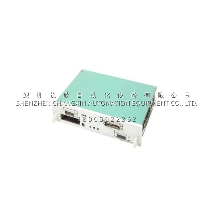
Application Scenarios
In a tandem cold-rolling mill still running S5-155U for its strip-handling line, the original software PID for inter-stand tension control lived inside the CPU 948’s OB1 — and at ~150 ms scan under full I/O load, the tension loop couldn’t catch nip-speed mismatches during acceleration, leaving coil ends with visible “snake” marks. The fix wasn’t a full S7 retrofit; it was slotting a Siemens 6ES5252-3AA13 into the same UR2 rack (the dry chassis we covered in the prior article), landing the load-cell amplifier’s ±10 V differential onto X6, and mapping the stand-drive tach (via an IP240 counter module on X4) as the speed feed-forward. The 6ES5252-3AA13 ran the tension PID at 5 ms sampling — completely decoupled from the CPU scan — and wrote the corrected torque bias back to the drive’s ±10 V summing node via X6 analog out. During a 1200 m/min acceleration test, the tension ripple dropped from ±12 % (software PID) to ±3.5 % (IP252 hardware loop). More practically, the 6ES5252-3AA13‘s 3AA13 A04+ firmware enabled the X4 link to the IP240 tach counter — so the IP240 counted encoder pulses while the 6ES5252-3AA13 consumed the speed word for feed-forward, splitting “count” from “control” across two submodules on the same backplane. For this mill, the 6ES5252-3AA13 turned a scan-limited PID into a deterministic 5 ms loop — no S7 migration required.
Parameter
| Main Parameters | Value/Description |
|---|---|
| Product Model | 6ES5252-3AA13 |
| Manufacturer | Siemens (SIMATIC S5) |
| Product Category | IP 252 Closed-Loop Control Module (Technology Submodule) |
| Compatible Hosts | S5-135U / S5-155U (central rack or EU expansion); S5-115U possible per config |
| Control Loops | 1 × independent closed-loop algorithm kernel |
| Control Algorithms | PID / PD / P (parametrizable); DRS controller structure stored in EPROM |
| Sampling Time | 1 ms – 250 ms (parametrized) |
| Setpoint Resolution | 12-bit + sign |
| Actual-Value Resolution | 12-bit + sign |
| Analog I/O (X6) | Diff. ±10 V, ±20 mA, 0–20 mA (config via submodule); AO ±10 V / 0–20 / 4–20 mA |
| Encoder I/F (X4) | Links to IP240 counter module for speed/position feed (3AA13 A04+ required for IP240 coupling) |
| Memory Submodule (X3) | 48-pin DIN 41612; accepts 32K EPROM (DRS structure) + 8K EEPROM (params) |
| Programming | STEP 5 + COM REG IP 252 or COM REG GRAPHIC IP 252 software package |
| Supply | 5 V DC from backplane + 24 V DC (M24V) for I/O |
| Mounting | 1 S5 rack slot |
| Operating Temp. | 0 °C to +60 °C |
| Discontinuation | Apr 2012 (spare-market only) |
Note: The “3AA13” suffix denotes version A04+ firmware on the submodule bus. Earlier IP252 batches (3AA11/3AA12) may lack X4→IP240 coupling — verify firmware label if your loop needs encoder speed feed-forward from an IP240.
Technical Principles and Innovative Values
- Innovation Point 1 – Hardware PID Decoupled from CPU Scan. The 6ES5252-3AA13 isn’t a “function block on a card” — it’s a microprocessor submodule that executes the closed-loop algorithm autonomously. The S5 CPU (948/945) writes setpoint + structure switches via the backplane once per OB1, but the 6ES5252-3AA13 integrates the error, updates output, and handles windup/limit every sampling tick (as fast as 1 ms) regardless of how loaded the CPU scan is. For tension, web, spindle, or hydraulic loops where 100+ ms OB1 kills stability, this is the architectural fix.
- Innovation Point 2 – DRS Controller Structure in 32K EPROM (X3 Submodule). Unlike transistor-output or AI modules where “configuration” is a few DIPs, the 6ES5252-3AA13 requires a memory submodule on X3: 32K EPROM holds the DRS (controller structure) — basically the firmware-level definition of which algorithm variants (PID with/without feed-forward, cascade, ratio, limiter topology) are available — while 8K EEPROM stores your tuned Kp, Tn, Tv, deadband, output clamp values. Swapping the EPROM changes the algorithm library without touching STEP 5 code. This submodule architecture is what separates IP252 from simpler analog-loop cards.
- Innovation Point 3 – X4 Encoder Link to IP240 for Speed Feed-Forward. The 6ES5252-3AA13 has a dedicated X4 37-pin interface that can couple to an IP240 counter/encoder module (the 3AA13 A04+ firmware enables this). In practice: IP240 counts the incremental encoder on a drive shaft; 6ES5252-3AA13 reads the speed word over X4 and uses it as feed-forward into the PID (e.g., tension loop on a unwind stand — you want the line speed in the numerator). One submodule counts, the other controls — both sit on the same S5 backplane, <1 µs handshake.
- Innovation Point 4 – 12-bit + Sign with Differential Analog I/O. The X6 25-pin analog interface delivers ±10 V / ±20 mA diff on the actual-value input and ±10 V / 4–20 mA on the output — 12-bit + sign both sides. “Diff” matters: in a rolling-mill pulpit 30 m from the stand, the ±10 V from a load-cell amp picks up VFD common-mode noise; differential reception on the 6ES5252-3AA13 rejects it. The 12+sign gives ~5 mV/LSB at ±10 V span — adequate for tension (where the 4–20 mA torque-bias output to the drive is the real actuator, not the ±10 V setpoint resolution).