Technical Specifications
| Parameter | Value |
|---|---|
| Product Model | 6ES5263-8MA12 |
| Manufacturer | Siemens |
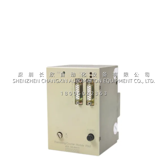
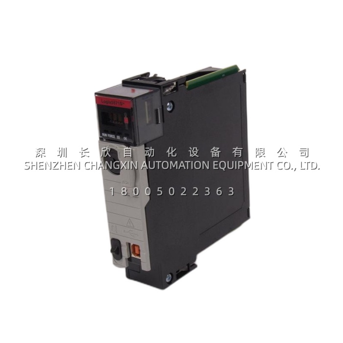
| Product Type | SIMATIC S5 IP 263 Positioning Module (2-channel) |
| Compatible System | S5-90U, S5-95U, S5-100U; ET 200U (2 slots, via IM 318-B) |
| Microprocessor | 80C52 / 80C32, 16 MHz |
| On-Board Memory | EPROM 64 KB / RAM 32 KB / EEPROM 1 Kbit |
| Positioning Channels | 2 independent axes |
| Digital Outputs per Ch. | 4 (Rapid Traverse / Creep Speed / CCW / CW) |
| Encoder Support | Incremental: 5 V RS422 differential, 24 V (asymmetrical); SSI absolute |
| Traversing Range | 8192 inc/rev × 2048 revolutions |
| Sensor Supply | 5 V DC / 300 mA + 24 V DC / 300 mA (on-board, short-circuit proof) |
| Positioning Modes | Rapid → Creep → Target approach; software limit switches; zero-speed monitor |
| Interpolation | Linear interpolation between two points |
| ET 200U Requirement | 2 slots on station, IM 318-B interface |
| Weight | ~0.5 kg |
| Operating Temperature | –25 … +60 °C (S5 compact family rating) |
| Mounting | S5-90U/95U/100U expansion bus / ET 200U rack |
Main Features and Advantages
Two independent axes with 4 DO per channel. The defining architecture of the Siemens 6ES5263-8MA12 is that each of its two channels manages a complete drive-interface quad: Rapid Traverse (full-speed approach), Creep Speed (fine-position window), Counter-Clockwise, and Clockwise rotation signals—logic-level outputs meant to drive interposing relays, contactor coils, or a drive’s enable inputs, not to carry motor current directly. For a rotary-index table, Channel 0 might drive the table’s servo or gear-motor through a relay bank: Rapid to spin to the next pocket, Creep to settle into the cam-detent, CW/CCW for direction. Channel 1 could simultaneously position a feeder slide on the same machine. Both run autonomously after the CPU writes PSET + VSET and issues START—the Siemens 6ES5263-8MA12 executes the ramp profile, watches the encoder, switches from Rapid→Creep at the configurable switchover point, and fires the “position reached” telegram when the axis lands in the target window. The CPU’s main scan is free for everything else.Triple encoder support: 5 V RS422, 24 V incremental, SSI absolute. The Siemens 6ES5263-8MA12 doesn’t lock you into one encoder tier. For precision axes (rotary-table with a 2048 P/R encoder, slide with a glass scale), the 5 V RS422 differential inputs reject noise on long cable runs—classic RS422, 5 V supplied from the module’s own 300 mA rail so you don’t need a separate encoder PSU. For rugged environments where a 5 V glass scale won’t survive (washdown, wood-chip conveyor, metal-chip slide), the 24 V incremental mode accepts rugged 24 V PNP/NPN encoder outputs, also drawing from the on-board 24 V / 300 mA rail. And for axes where “power-up, know where I am” matters—turret tool-post, index table with absolute homing requirement—the SSI (Synchronous Serial Interface) absolute-encoder path reads a 13-bit (or higher, depending on encoder) position word on every scan without needing a home run. The traversing range of 8192 × 2048 = ~16.8 M counts means multi-turn absolute encoders are fully exploited.Rapid → Creep → Target profile with software limit switches. The Siemens 6ES5263-8MA12 implements the classic machining-profile state machine: after START, the axis accelerates to Rapid traverse toward the target; when it crosses the switchover/cutoff difference (configurable in the DB), it drops to Creep speed; it then monitors approach and, when the encoder count lands within the target window, asserts the “position reached” status and sends the telegram to the CPU (via backplane on S5-100U, or via IM 318-B on ET 200U). Software limit switches are programmable per channel so the axis won’t overshoot past a mechanical stop even if the CPU ladder mis-addresses. Zero-speed monitoring is built in—the module can hold Creep until the encoder delta falls below a threshold, preventing “coast-past” on high-inertia loads. For plants whose original EPC tuned these DB values in the late 1990s, the Siemens 6ES5263-8MA12 preserves that tuning byte-for-byte across a replacement—no re-commissioning the ramp if the spare is pre-loaded from the live DB.Linear interpolation between two points. Beyond single-axis point-to-point, the Siemens 6ES5263-8MA12 supports linear interpolation—useful on small XY gantry heads, twin-slide feeders, and diagonal traverse on a cut-to-length shear where the carriage and the hold-down need to coordinate. It’s not 3-axis CNC—this is S5 compact, not Sinumerik—but for a packaging-machine registration knife that needs the film-feed slide and the cross-cut carriage to hit a diagonal registration mark, the IP 263’s interpolation is enough. The STEP 5 FB set (PSET/VSET/START/MONITOR) abstracts this cleanly—the CPU ladder just says “move Axis 0 and 1 together to X,Y” and the Siemens 6ES5263-8MA12 handles the coordinated ramp.On-board sensor supplies eliminate encoder PSU. A detail small on paper but big in a cramped S5-100U panel: the Siemens 6ES5263-8MA12 carries 5 V / 300 mA and 24 V / 300 mA short-circuit-protected (but not overload-protected externally—don’t hang extra load) sensor rails right on the module, sourced from the S5-100U expansion bus 5 V / 24 V distribution. A typical incremental encoder draws 60–150 mA; an SSI absolute draws 50–100 mA; so one IP 263 can feed both its channel encoders from its own supplies in most small-machine builds. This collapses what would otherwise be a small DIN-rail encoder PSU (another SITOP bite, another terminal row) out of the BOM. For skid OEMs standardizing on S5-100U + IP 263, this integration is why the combo shows up in packaging-machine local panels and converter-aux slides.MA12 firmware and the MA13 trap. A storeroom note worth calling out: the Siemens 6ES5263-8MA12 (and the earlier -8MA11) run the “original” IP 263 FB/DB map where the “PEH” (Position Erreicht = position reached) status bit lives in byte 1 of the interface DB. The later -8MA13 revision moved PEH to “REG 25” (a different status-register mapping) and changed the toggle-bit protocol. Siemens’ own FAQ states: the MA11/MA12 example program does not run on MA13; conversely, MA11/MA12 can run on the MA13 example program (backward-compatible on the SW side, but not forward). Practically: if your plant’s S5-100U project was written for -8MA12 (most were, through the 2000s), swapping in an -8MA13 requires updating the FB/DB calls in STEP 5—not a drop-in. Swapping MA12 ↔ MA11 is a drop-in. When buying a Siemens 6ES5263-8MA12 as spare against an MA11 live unit, you’re safe; buying MA13 to replace a failed MA12 requires a project tweak. This is the #1 “why did the new positioning module break the ladder” root cause in the aftermarket.