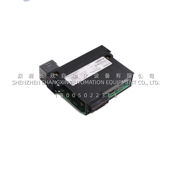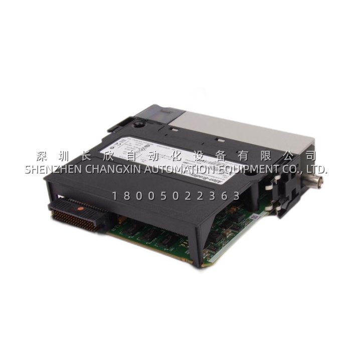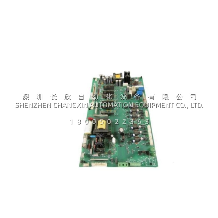
Parameter
| Main Parameters | Value / Description | What it means on site |
|---|---|---|
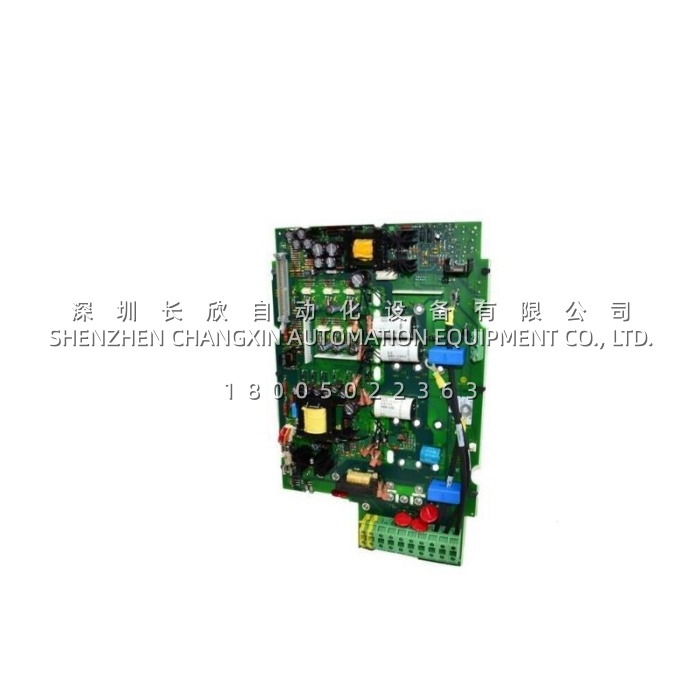
| Product Model | 1336-BDB-SP29D (Rockwell P/N 74101-169-53) | Order by the full code including revision suffix; the internal number appears on some labels |
| Manufacturer | Allen-Bradley / Rockwell Automation | Original equipment manufacturer for the 1336 drive family |
| Product Category | Gate drive / base drive PCB assembly | Interfaces control logic to IGBTs; one board required per drive |
| Voltage Class | 460 V AC (input range commonly stated as 380-480 V AC) | Must match the drive supply; a 230 V class drive uses a different board |
| Associated Drive Rating | 75 HP (63 kW / approx. 55 kW depending on source) | Linked to a specific power section; do not fit to a higher-rated frame |
| Compatible Frames | Commonly supplied for Frame D; some listings state frames A through E | Confirm against the drive nameplate, since frame size decides the board |
| Compatible Drive Series | 1336 PLUS, PLUS II, FORCE, IMPACT, REGEN | 1336 IMPACT and PLUS II should be verified by catalog number before ordering |
| Primary Function | PWM amplification, gate pulse generation, feedback and control interface | Converts logic-level signals into high-current gate drive |
| Drive Channels | Six independent channels for the three-phase upper and lower IGBTs | One channel pair per inverter phase |
| Isolation | Reinforced galvanic isolation between control electronics and DC bus | Stops high-voltage transients reaching the control board |
| Protection Features | IGBT desaturation detection, short-circuit protection, overcurrent, overvoltage, surge, under-voltage lockout (UVLO) | Detects an IGBT coming out of saturation and commands a soft shutdown before the module is destroyed |
| Signal Interface | Fibre-optic receivers or high-grade opto-couplers, multi-pin headers, ribbon and edge connectors | Noise-immune command path and simple plug-in replacement |
| Board Material | FR4 epoxy glass laminate | Standard industrial PCB construction |
| Physical Dimensions | Approx. 39.3 × 24.4 × 4 cm | Check clearance in the power stack before ordering |
| Weight | Approx. 1.26 kg (some sources list 0.82 kg) | Variation between revisions and packaging |
| Shock / Vibration | 15G at 11 ms operating, 30G non-operating; vibration up to 5G | Survives typical industrial cabinet and plant environments |
| Operating / Storage Temperature | 0 °C to 40 °C or 50 °C operating depending on source; storage -40 °C to 85 °C | Keep within a ventilated drive enclosure |
| Humidity | 5 to 95% non-condensing | Standard for indoor drive cabinets |
| Lifecycle Status | Discontinued by the manufacturer; supplied as new surplus or tested refurbished | Treat as an installed-base maintenance spare |
Technical Principles and Innovative Values
Innovation Point 1 – Isolation barrier inside the power stage: 1336-BDB-SP29D carries reinforced galvanic isolation between the low-voltage control side and the DC bus. That barrier is what keeps a switching transient on the power side from propagating back into the control electronics, which is precisely the failure mode that turns a small fault into a whole-drive replacement.Innovation Point 2 – Desaturation detection as real IGBT protection: the board monitors the collector-emitter voltage of each IGBT while it is conducting. If an overcurrent or short circuit pulls the device out of saturation, 1336-BDB-SP29D sees the voltage rise and initiates a controlled soft shutdown rather than letting the module fail destructively. Preventing one IGBT power module failure pays for a spare board many times over.Innovation Point 3 – Under-voltage lockout: if the gate drive supply sags, an IGBT can turn on only partially and dissipate destructive amounts of heat. 1336-BDB-SP29D holds the devices off until the supply is valid, which removes a whole category of unexplained power-stage failures during brownouts and start-up.Innovation Point 4 – Noise-immune command path: PWM commands reach the board through fibre-optic or high-grade opto-coupler interfaces, so the switching pattern is not corrupted by the electrical noise that surrounds a 75 HP inverter. Clean gate timing means cleaner output waveform, less motor heating and lower EMI.Innovation Point 5 – Revision-specific engineering: the SP29D suffix is not decoration. Gate drive timing, layout and signal paths differ between 1336-BDB-SP29D and its sibling revisions, and a board that looks identical can misbehave in the power stack. Matching the revision keeps protection logic and switching behaviour exactly as the drive was designed and tested.
Application Cases and Industry Value
Case 1 – Water and wastewater pump station: A plant with several 1336 PLUS drives on raw water pumps kept one tested 1336-BDB-SP29D in the maintenance store as part of its critical spares list. When a drive tripped on a power-stage fault during peak demand, technicians isolated the drive, confirmed the fault followed the gate drive rather than the IGBT stack, and swapped the board in under two hours. The pump returned to service the same shift, and the plant avoided both an emergency drive rental and a process upset. The documented saving was the difference between a board and a complete drive with installation and reprogramming.Case 2 – Steel mill material handling: A conveyor drive on a 1336 platform began showing intermittent gate-related faults that cleared on reset – the classic symptom of a degrading gate drive board rather than a hard failure. Rather than waiting for the drive to stop completely, maintenance scheduled a board change during the next planned shutdown and installed 1336-BDB-SP29D after confirming the frame size and voltage class on the nameplate. The intermittent faults disappeared. The value here was in converting an unpredictable failure into a planned intervention, which for a continuous process line is worth more than the hardware itself.