Product Overview
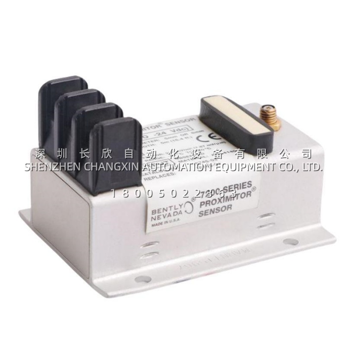
The Bently Nevada 991-01-XX-01-05 is a two-wire, loop-powered transmitter that converts the signal from a single 3300 NSv eddy-current proximity probe into a 4 to 20 mA output proportional to the axial position of a shaft. It belongs to the Bently Nevada 991 Thrust Transmitter family, a line intended for original equipment manufacturers of centrifugal air compressors, small pumps, motors and fans who want one proportional axial displacement signal going into a PLC, DCS or packaged machinery control panel instead of a dedicated monitor rack. The Proximitor driver electronics are built into the housing, so there is no separate signal conditioner, no rack slot and no configuration software to buy.Where a vibration transmitter reports how much a shaft is moving, the Bently Nevada 991-01-XX-01-05 reports where the rotor sits along its axis, which is the measurement that protects a thrust bearing from being destroyed in seconds. The transmitter is designed for machines with fluid-film thrust bearings and covers up to 1.2 mm (50 mils) of total thrust movement, with a usable Prox Out linear range of 0.25 to 1.65 mm (10 to 65 mils). The code itself carries the configuration: the first pair selects the full-scale range, “XX” is the total electrical system length of the matched probe and extension cable — normally 5.0 m or 7.0 m — “01” in the third position specifies 35 mm DIN rail clips, and “05” is the agency approval package.That last digit is the reason this variant is specified. The Bently Nevada 991-01-XX-01-05 carries CSA Division 2, ATEX Zone 0, ATEX Zone 2 and ABS maritime approvals, so the same part number can be installed in a hazardous area onshore, on an offshore platform or on a vessel without changing the design. One caveat worth stating on the range: the published 991 datasheet lists the standard full-scale options as 06 (0.6-0-0.6 mm) and 25 (25-0-25 mils), while the “01” prefix appears in channel and OEM configurations; confirm the scaling against the original order code before substituting.
Technical Specifications
| Parameter Name | Parameter Value |
|---|---|
| Product Model | 991-01-XX-01-05 |
| Manufacturer | Bently Nevada (a Baker Hughes business), made in U.S.A. |
| Product Type | 2-wire, loop-powered thrust / axial shaft displacement transmitter |
| Series | 991 Thrust Transmitter |
| Full-Scale Option | 01 thrust range; standard datasheet options are 06 = 0.6-0-0.6 mm and 25 = 25-0-25 mils (confirm scaling against the original order code) |
| System Length Option | XX = 50 (5.0 m / 16.4 ft) or 70 (7.0 m / 23.0 ft), probe plus extension cable |
| Mounting Option | 01 = 35 mm DIN rail clips (02 = bulkhead screws, 03 = DIN clips and screws) |
| Agency Approval Option | 05 = CSA Division 2, ATEX Zone 0, ATEX Zone 2, includes ABS maritime approval |
| Input | One non-contacting 3300 NSv proximity probe with matching extension cable |
| Signal Output | 4 to 20 mA DC proportional to axial position, 2-wire configuration |
| Supply Voltage | +12 to +35 Vdc at the transmitter terminal |
| Loop Accuracy | Within ±1.5 % of full-scale range, typical |
| Maximum Loop Resistance | 1,000 Ω including cable at 35 Vdc |
| Current Limiting | 23 mA typical |
| Zero and Span | Non-interacting external potentiometers |
| Not OK / Signal Defeat | Output falls below 3.6 mA within 100 µs; restored within 0.1 s |
| Prox Out Linear Range | 0.25 to 1.65 mm (10 to 65 mils); scale factor 7.87 mV/µm (200 mV/mil) ±6.5 % |
| Prox Out Impedance | 10 kΩ, calibrated for a 10 MΩ load |
| Minimum Target Size | 9.5 mm diameter |
| Operating Temperature | −35 °C to +85 °C; storage −51 °C to +100 °C |
| Humidity | Up to 100 % condensing, non-submerged; potted construction |
| Dimensions / Weight | Approximately 100.1 × 73.9 × 53.3 mm; transmitter 0.43 kg, typical system 0.82 kg |
Main Features and Advantages
Integrated Proximitor electronics: The 991-01-XX-01-05 contains the oscillator and demodulator that would otherwise be a separate Proximitor box, which removes a device, a mounting plate, a power feed and a full set of terminations from the installation. On a compressor skid where the junction box is already crowded, this is the difference between adding a thrust point and rebuilding the panel.Fault behaviour that protects the machine from bad data: A failed probe or a loose connector is the classic source of a false high reading. When the 991-01-XX-01-05 detects a Not OK condition, it drives the loop below 3.6 mA within 100 µs and restores within 0.1 s once the fault clears. A control system written to treat under-range current as an instrument fault rather than a safe position will annunciate a bad transmitter instead of tripping on a phantom thrust excursion. A power-up inhibit circuit holds the output below 3.6 mA for two to three seconds after energising, which stops line transients during a plant restart from reaching the alarm comparator.Diagnostics without opening the loop: The 991-01-XX-01-05 provides a non-isolated buffered dynamic signal on PROX OUT and COM terminals and on a coaxial connector, at a nominal 200 mV/mil. Reading the gap voltage there tells a technician whether the probe is sitting in the middle of its linear range or has drifted toward the target, which is the first thing to check on any suspicious reading. Because that output shares a reference with the current loop, grounded AC-powered instruments must be connected through an isolating adapter such as the 122115-01 Test Adapter.Field calibration and approvals coverage: A test input pin allows the whole 4 to 20 mA loop to be verified with a variable DC source without moving the shaft, and zero and span are non-interacting external adjustments. The 05 approvals package is what lets the 991-01-XX-01-05 be used in Zone 0 and Zone 2 hazardous areas and on ABS-classed vessels, which removes the need to stock separate variants for onshore and marine projects.