Application Scenarios
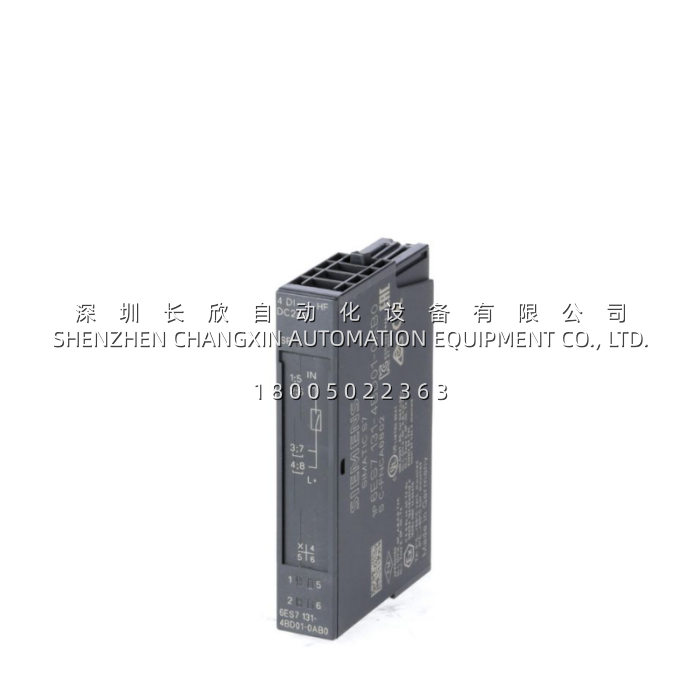
In a regional water-treatment plant midway through a TXP-to-SPPA-T3000 migration, the instrumentation team faced a classic brownfield puzzle: the existing 6DS1602-8BA 32-point DI carriers in the Teleperm M rack were being decommissioned, but a small satellite skid — 400 m away from the main AP cabinet — still needed 4 local DI points for hand-off-auto selectors, high-level float switches, and a local E-stop mushroom. Running new 32-point homerun cables back to the central rack was cost-prohibitive. The fix: mount an IM 151-3 PN head on a local DIN rail at the skid, clip a Siemens 6ES7 131-4BD01-0AA0 onto its TM-P15S23 terminal base, and land the four field wires right there. The 6ES7 131-4BD01-0AA0‘s 20.4–28.8 V DC tolerance absorbed the skid’s lightly loaded 24 V auxiliary rail (fed by the same 6EP1332-2BA10 PSU family we covered earlier), and the 2-wire sensor support let the float switches wire directly without extra marshalling. During commissioning, one float’s NAMUR-style proximity loop showed intermittent “1” flicker — the 6ES7 131-4BD01-0AA0‘s per-channel green LED + the 2 ms minimum input delay (parametrized to 4 ms in TIA Portal) debounced it cleanly, no spurious alarm in the SCADA. For this plant, the 6ES7 131-4BD01-0AA0 was the cheapest 4-meter of copper they didn’t have to pull.
Parameter
| Main Parameters | Value/Description |
|---|---|
| Product Model | 6ES7 131-4BD01-0AA0 |
| Manufacturer | Siemens (Factory Automation – SIMATIC) |
| Product Category | Electronic Module – Digital Input (ET 200S “5” series) |
| DI Channels | 4 × 24 V DC, standard (IEC 61131 Type 1) |
| Rated Input Voltage | 24 V DC (allowable 20.4 – 28.8 V DC) |
| Input Threshold | “0” = –30 to +5 V / “1” = 15 to 30 V |
| Input Current (signal 1) | Typ. 7 mA @ 24 V DC |
| Input Delay | Min. 2 ms / Typ. 3 ms / Max. 4.5 ms (not parametrized; fixed standard) |
| Sensor Supply (L+) | Max. 500 mA (L+ –0.5 V under load) |
| Wiring | Shielded ≤ 1000 m, unshielded ≤ 600 m; 2-wire sensors supported |
| Isolation | Channel ↔ backplane bus (500 V DC test); no ch↔ch isolation |
| Dimensions (W×H×D) | 15 mm × 81 mm × 52 mm |
| Weight | Approx. 35 g (sold 5 pcs/pack) |
| Mounting | Snap-on ET 200S terminal module base (e.g. TM-P15S23) |
Note: This is the “standard” 4-DI submodule, not the failsafe (F-DI) variant. For SIL 3 / PL e applications, look to the 6ES7 138-4FA series instead. The 6ES7 131-4BD01-0AA0 is intended for general-purpose DI where the upstream IM and controller handle safety classification.
Technical Principles and Innovative Values
- Innovation Point 1 – 15 mm “5-Series” Slim Form Factor. While the older ET 200S “4-series” electronic modules sat at 30 mm width, the 6ES7 131-4BD01-0AA0 belongs to the newer “5-series” at 15 mm — exactly half the footprint. In a typical ET 200S station with PM-E power module + IM + 6–8 electronic modules, switching to 5-series can reclaim 75–105 mm of DIN width, which matters when the cabinet was originally specced for a smaller I/O count and later grew.
- Innovation Point 2 – Integrated 500 mA Sensor Aux Supply. The 6ES7 131-4BD01-0AA0 doesn’t just read 24 V DC — it can source up to 500 mA on its L+ sensor supply output (L+ minus ≤0.5 V drop). This lets you power lightweight 2-wire DC sensors (NAMUR proximity, photoelectric, paddle-flow) directly from the module without a separate terminal +24 V tap, reducing marshalling density.
- Innovation Point 3 – Channel-to-Backplane Isolation with 500 V DC Proof. Individual DI channels aren’t isolated from each other (common COM), but each channel group is galvanically separated from the ET 200S backplane/profibus side at 500 V DC test voltage. In a cabinet where the 24 V field loop and the PROFIBUS DP/PN bus share ground but you want to contain a 24 V transient — say, a solenoid inductive kick — the 6ES7 131-4BD01-0AA0 keeps the backplane clean.
- Innovation Point 4 – Per-Channel Green LED + Fixed Debounce Timing. Front-panel LEDs (one per DI channel, green) give at-a-glance contact status without opening TIA Portal. The input delay is fixed (not software-parametrizable on this standard submodule — min 2 ms / typ 3 ms / max 4.5 ms) which is deliberately conservative: it rejects contact bounce from mechanical limit switches and relay aux contacts without needing the engineer to remember a parameter download.