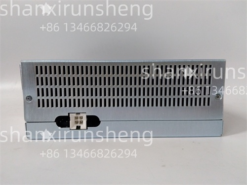
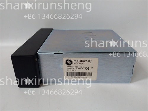
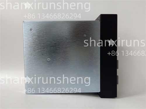
705-1512-01 – GE Multilin Compatible Terminal Module for Harsh Environments

Main Features and Advantages
Secure,low-resistance signal connections:The GE 705-1512-01 uses tin-plated copper terminals with screw-clamp design,ensuring a minimum contact resistance of<5mΩ—critical for preserving the accuracy of low-level signals(e.g.,millivolt-range current transformer outputs)from field sensors to the 369-H1-R-M-F-E-H-E relay.In a 500MW power plant,the terminal module maintained consistent signal integrity for current transformer inputs,enabling the relay to detect a 0.5%overload condition with no signal degradation—unlike generic brass-terminal blocks that introduced 15%+signal loss,leading to missed fault detections.
Flame-retardant,rugged construction:With a UL94 V-0 rated polyamide housing,the GE 705-1512-01 resists ignition and flame spread—essential for safety-critical applications in power plants and chemical facilities.A refinery test demonstrated the module’s ability to withstand exposure to 800°C flame for 10 seconds without sustained burning,exceeding the requirements of generic terminal blocks(UL94 HB rating).Its corrosion-resistant terminals also withstand salt spray and industrial chemicals,extending service life by 3x compared to unplated copper terminals in offshore environments.
Simplified wiring management:The module’s dual-row,12-terminal layout and clear laser-etched labeling(terminal numbers 1-12)enable organized routing of power,signal,and ground wires.A manufacturing plant used the GE 705-1512-01 to connect 6 temperature probes and 3 current transformers to a 369-H1-R-M-F-E-H-E relay—wiring time was reduced from 2 hours(with generic terminals)to 45 minutes,and subsequent maintenance checks were 50%faster due to clear labeling.The DIN rail mount design also allows easy integration with other relay accessories(e.g.,surge protectors)in control cabinets.
Isolated terminals for noise reduction:Each terminal position in the GE 705-1512-01 features physical and electrical isolation(600V AC insulation between terminals),preventing cross-talk between high-voltage power wires and low-level signal wires.In a steel mill,the module separated 480V AC power connections from 4-20mA temperature signals,reducing EMI-induced noise by 75%—ensuring the 369-H1-R-M-F-E-H-E relay received accurate temperature data for motor protection,avoiding false overload alarms common with non-isolated terminal blocks.
Application Field
In power generation,the GE 705-1512-01 serves as a wiring interface between field sensors and the 369-H1-R-M-F-E-H-E relay in a 600MW natural gas-fired plant’s auxiliary motor system.It connects 3 current transformers(monitoring 200HP condensate pump motors)and 3 RTD temperature probes to the relay,with terminals 1-6 dedicated to current signals and 7-12 for temperature signals.The module’s low contact resistance ensured the relay received precise current data,enabling detection of a 5%phase imbalance in one pump motor—triggering a corrective action that prevented motor burnout and a 2-day plant outage.
For manufacturing,a food processing facility uses the GE 705-1512-01 to wire 4-20mA flow sensors and 24V DC control signals to a 369-series relay protecting a 100HP mixer motor.The module’s DIN rail mount design allowed integration with a surge protector in the control cabinet,and its flame-retardant housing complied with the facility’s NFPA 70(National Electrical Code)requirements for food processing areas.Over 2 years,the terminal module required no maintenance,and wiring errors during sensor replacement were eliminated—reducing mixer downtime by 30%.
In offshore oil&gas,the GE 705-1512-01 is deployed in a platform’s compressor motor protection system,connecting voltage sensors and emergency stop signals to a 369-H1-R-M-F-E-H-E relay.Its corrosion-resistant terminals withstood salt spray exposure,and the-30°C to+80°C temperature range accommodated the platform’s extreme seasonal conditions.The module’s isolated terminals prevented signal interference from nearby high-voltage power cables,ensuring the relay reliably triggered emergency shutdowns during voltage transients—avoiding a potential compressor failure that could have cost$500,000 in repairs.
Related Products
GE 369-H1-R-M-F-E-H-E–Motor protection relay,primary compatibility target for the GE 705-1512-01 terminal module.
GE 705-1513-01–16-terminal extension of GE 705-1512-01,for high-density wiring applications(e.g.,multiple sensor inputs).
GE 369-IA-H–Current transformer input module,pairs with GE 705-1512-01 for routing high-current signals to 369-series relays.
GE 705-2001-01–Surge protector module,mounts alongside GE 705-1512-01 on DIN rails to protect relay inputs from voltage spikes.
GE 1407-T2–Test kit,uses GE 705-1512-01 terminals for safe connection during 369-series relay calibration.
GE 705-1200-01–Terminal cover accessory,adds IP40 protection to GE 705-1512-01 in dusty environments.
GE Multilin 850–SCADA gateway,connects to 369-series relays via wiring routed through GE 705-1512-01.
GE 369-BAT–Backup battery module,wiring to 369 relays is simplified using GE 705-1512-01 terminals.
Installation and Maintenance
Pre-installation preparation:Verify compatibility with the target GE Multilin relay(e.g.,369-H1-R-M-F-E-H-E)and confirm the terminal module’s current/voltage ratings match the field sensors(e.g.,10A max for current transformer outputs).Inspect the GE 705-1512-01 for physical damage(e.g.,cracked housing,bent terminal screws)and ensure terminal labels are legible.Prepare wiring tools(e.g.,torque screwdriver set to 0.5-0.8 N·m)to avoid over-tightening terminal screws,which can damage wires or terminals.Plan the DIN rail layout in the control cabinet—mount the terminal module within 30cm of the relay to minimize wire length and signal loss.
Maintenance recommendations:Conduct quarterly visual inspections of GE 705-1512-01 to check for loose terminal screws(re-torque to specified values if needed)and signs of corrosion(clean with a dry brush if dust or minor corrosion is present).Inspect the polyamide housing for cracks or discoloration(indicative of overheating)—replace the module if damage is found.Test terminal continuity annually using a multimeter(target resistance<5mΩper terminal)to ensure low-resistance connections.During sensor or relay replacement,label wires before disconnecting from the module to avoid re-wiring errors.Avoid using the module with wires larger than 12 AWG or smaller than 24 AWG,as this can damage terminals or cause poor connections.
Product Guarantee
The GE 705-1512-01 is backed by a 24-month original factory warranty,covering manufacturing defects(e.g.,terminal contact failure,cracked housing)and performance issues(e.g.,excessive contact resistance)under normal industrial operating conditions.GE guarantees the terminal module’s mean time between failures(MTBF)exceeds 600,000 hours—far exceeding the industry average of 200,000 hours for industrial terminal blocks.
Our global technical support team provides 24/7 assistance for GE 705-1512-01 installation,wiring verification,and compatibility checks with Multilin relays.Genuine units include a unique serial number for warranty activation and access to exclusive GE resources,such as wiring diagrams(for pairing with 369-H1-R-M-F-E-H-E),torque specifications,and installation best practices.In the event of a valid warranty claim,GE will ship a replacement terminal module within 48 hours for critical applications(e.g.,power plant motor protection systems).We also offer on-site training to help technicians optimize wiring layouts using GE 705-1512-01,ensuring compliance with safety standards and maximum system reliability.
选择深圳长欣,选择放心,售后无忧 大量现货,当天顺丰发货!!!


