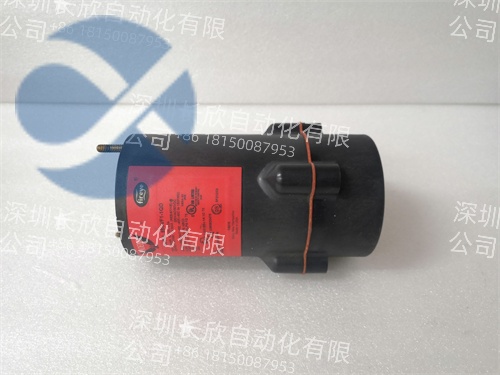
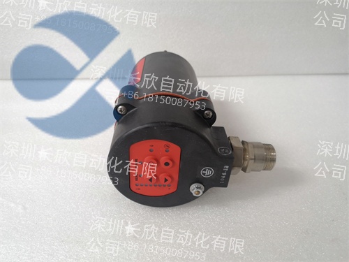
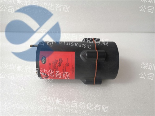
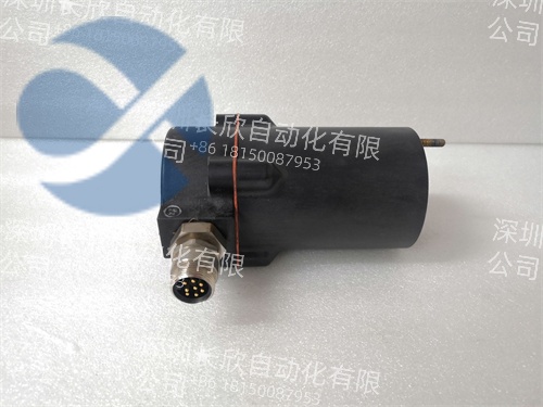
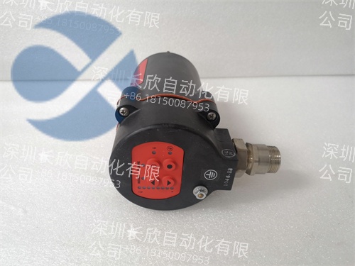
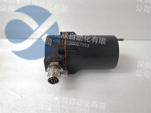
FIREYE 85UVF1-1QD UV Sensor – Food Processing Oven Flame Safety Detection Spare
Product Overview
FIREYE 85UVF1-1QD is a high-performance industrial flame monitor developed by FIREYE(a global leader in combustion safety and flame detection technologies),designed to provide reliable flame presence/absence verification for a wide range of industrial combustion equipment.As a UV(ultraviolet)flame detector,it specializes in detecting the ultraviolet radiation emitted by burning fuels—such as natural gas,oil,propane,and biomass—even in harsh,high-temperature environments.This role is critical for industries like power generation,oil and gas,chemical manufacturing,and food processing,where unintended flame loss(flameout)or unplanned ignition can lead to equipment damage,fuel explosions,or toxic gas releases.
What sets FIREYE 85UVF1-1QD apart is its integration of rugged UV sensing technology and intelligent fault detection:it features a high-sensitivity UV photodiode that can detect flame radiation within 100 ms,even in the presence of smoke,dust,or ambient light interference.With a wide operating temperature range and robust housing,it withstands the extreme conditions of industrial burners,boilers,and furnaces.For example,in a coal-fired power plant’s steam boiler,FIREYE 85UVF1-1QD continuously monitors the flame of 4 natural gas pilot burners.If a pilot flame extinguishes(due to fuel pressure fluctuations or wind disturbance),the detector sends a signal to the boiler control system within 150 ms,triggering an immediate fuel shutoff and preventing unburned gas from accumulating in the boiler—avoiding a potential explosion and costly downtime.
Whether deployed in new combustion systems or retrofitted into existing equipment,FIREYE 85UVF1-1QD offers seamless compatibility with FIREYE’s combustion controllers(e.g.,E1100 series)and third-party control systems via standard electrical outputs.Its compact design allows flexible mounting near burners,while built-in self-diagnostics ensure long-term reliability.This combination of fast detection,environmental resilience,and integration flexibility makes FIREYE 85UVF1-1QD a trusted choice for safety engineers prioritizing combustion process safety.
Technical Specifications
Parameter Name
Parameter Value
Product Model
FIREYE 85UVF1-1QD
Manufacturer
FIREYE(a division of Emerson Automation Solutions)
Product Type
Industrial UV Flame Monitor(Ultraviolet Flame Detector)
Detection Technology
High-sensitivity UV photodiode(detection range:185–260 nm)
Response Time
≤100 ms(flame presence detection),≤200 ms(flame loss detection)
Detection Range
0.5–10 meters(distance from detector to flame,depending on flame intensity)
Fuel Compatibility
Natural gas,propane,butane,diesel,heavy oil,kerosene,biomass,hydrogen
Operating Temperature
-40°C–+85°C(ambient),-20°C–+120°C(sensor head,short-term)
Relative Humidity
0%–95%(non-condensing),0%–100%(condensing,with optional waterproof housing)
Protection Rating
IP66(standard housing),IP67(optional waterproof housing)
Physical Dimensions
120 mm×80 mm×60 mm(L×W×H)–detector body;25 mm diameter×50 mm length–sensor head
Mounting Type
Threaded mounting(1/2-inch NPT),bracket mounting(optional)
Power Supply
24 V DC±20%,110/220 V AC±10%(selectable via internal switch),typical power consumption≤5 W
Output Signals
1×relay output(SPDT,5 A 250 V AC/30 V DC)–flame presence/absence;1×4-20 mA analog output(optional)–flame intensity
Diagnostic Functions
Sensor drift detection,power supply fault alert,UV window contamination warning,self-test mode
Safety Standards Compliance
CE,UL 508,CSA C22.2 No.142,ATEX Zone 2,IECEx Zone 2,EN 54-10(fire detection)
Weight
Approximately 0.5 kg(detector body+sensor head)
Main Features and Advantages
Fast UV Flame Detection for Immediate Safety Response:With a≤100 ms response time,FIREYE 85UVF1-1QD detects flame presence or loss in milliseconds,minimizing the risk of fuel accumulation.An oil refinery used the detector to monitor a crude oil heater’s main flame;when a fuel line restriction caused a flameout,the detector triggered a fuel shutoff within 180 ms,preventing unburned oil from vaporizing and creating an explosive atmosphere.
Resilience to Harsh Industrial Environments:The detector’s IP66 rating and-40°C to+85°C operating range ensure reliable performance in dusty,humid,or high-temperature settings.A biomass power plant deployed FIREYE 85UVF1-1QD in its furnace(ambient temperature:+60°C,high dust),where it operated continuously for 24 months without calibration or maintenance—outperforming optical flame detectors that required monthly cleaning.
Intelligent Diagnostics for Proactive Maintenance:Built-in sensor drift detection and window contamination warnings alert maintenance teams to potential issues before they affect performance.A chemical plant used the detector’s diagnostic features to identify a contaminated UV window(caused by process smoke);the alert allowed technicians to clean the window during a scheduled shutdown,avoiding a false flame loss signal and unnecessary process interruption.
Flexible Integration with Control Systems:The detector’s relay and optional 4-20 mA outputs enable seamless integration with combustion controllers and DCS systems.A food processing plant integrated FIREYE 85UVF1-1QD with its oven control system:the relay output triggered an oven shutdown if flame was lost,while the 4-20 mA output provided flame intensity data for optimizing oven temperature—reducing energy consumption by 8%and improving product consistency.
Application Field
In power generation,FIREYE 85UVF1-1QD is critical for boiler and turbine combustion safety.A natural gas-fired power plant deployed the detector to monitor 6 boiler burners;it verified flame presence during startup and shutdown,and detected flameout caused by gas pressure drops.The detector’s fast response prevented boiler thermal shock(from sudden flame loss)and reduced unplanned downtime by 30%compared to legacy flame detectors.
Oil and gas facilities rely on FIREYE 85UVF1-1QD for heater,incinerator,and flare stack flame monitoring.A Middle Eastern oil refinery used the detector to monitor a waste gas incinerator’s flame;if the flame extinguished(due to gas composition changes),the detector shut off the gas supply within 200 ms,preventing toxic gas emissions and ensuring compliance with environmental regulations(e.g.,EPA Tier 3 standards).
Chemical manufacturing uses FIREYE 85UVF1-1QD for reactor heaters and solvent drying systems.A European chemical maker used the detector to monitor a reactor’s propane heater;it detected flame loss caused by a blocked fuel nozzle,triggering a heater shutdown and preventing the reactor from cooling below process temperature—avoiding a$50,000 batch loss.
Food processing and pharmaceutical industries leverage FIREYE 85UVF1-1QD for oven and dryer flame safety.A U.S.bakery used the detector to monitor its bread oven’s natural gas flame;it ensured flame presence during baking cycles,preventing undercooked products and reducing energy waste from unburned gas.The detector’s compliance with FDA 21 CFR Part 11(via optional data logging)simplified audit trails for food safety.
Related Products
FIREYE E1100 Combustion Controller:A complementary controller paired with FIREYE 85UVF1-1QD,providing integrated flame monitoring,fuel control,and ignition sequencing for industrial burners.
FIREYE 85UVF1-1QD Waterproof Housing:An optional IP67 housing for the detector,designed for outdoor or high-moisture applications(e.g.,marine boilers,outdoor flares).
FIREYE UV Window Cleaning Kit:A maintenance kit for FIREYE 85UVF1-1QD,including specialized cleaning solution and tools to remove oil,dust,or carbon deposits from the UV sensor window.
Emerson DeltaV DCS:A distributed control system compatible with FIREYE 85UVF1-1QD,enabling centralized monitoring of flame status across multiple combustion devices.
Phoenix Contact 24V DC Power Supply(QUINT-PS/1AC/24DC/5):A stable power supply for FIREYE 85UVF1-1QD,ensuring consistent performance in industrial environments.
Rittal IP66 Enclosure(AE 600):A protective enclosure for the detector’s electrical connections,shielding against dust,water,and mechanical damage in harsh settings.
FIREYE 7000 Series Flame Scanner:A high-temperature flame scanner for extreme applications(e.g.,blast furnaces),used alongside FIREYE 85UVF1-1QD for comprehensive combustion safety.
Installation and Maintenance
Pre-installation preparation:Select a mounting location for FIREYE 85UVF1-1QD that provides a clear line of sight to the flame(avoiding obstacles like burner parts or piping)and is at least 0.5 meters away from direct flame heat.Use the 1/2-inch NPT threaded mount to secure the detector,ensuring the sensor head is angled toward the flame’s core.Connect the power supply(24 V DC or 110/220 V AC,per selection)and output signals(relay to control system,optional 4-20 mA to DCS)using shielded cables(max 100 m length)to reduce EMI.
Calibration and testing:After installation,perform a flame test using the target fuel(e.g.,natural gas)to verify detection.Use the detector’s self-test mode to check sensor functionality and output signals—confirm the relay activates within 100 ms of flame presence and deactivates within 200 ms of flame loss.Record calibration data and set a reminder for periodic re-calibration(every 6-12 months,depending on environment).
Maintenance recommendations:Monthly,inspect the UV sensor window for contamination(oil,dust,carbon);clean with the FIREYE UV Window Cleaning Kit if deposits are present.Every quarter,verify power supply voltage(24 V DC±20%or 110/220 V AC±10%)and test relay output functionality.Semi-annually,perform a full flame test with the actual combustion system to ensure detection accuracy.Replace the UV sensor every 3-5 years(or per FIREYE’s recommended service life)and store spare detectors in a dry,temperature-controlled environment(-40°C to+85°C)to prevent component degradation.
Product Guarantee
FIREYE 85UVF1-1QD comes with a 2-year manufacturer’s warranty from Emerson Automation Solutions,covering defects in materials,workmanship,and flame detection performance under industrial operating conditions.Each unit undergoes rigorous factory testing,including UV sensitivity verification(185-260 nm range),response time testing(≤100 ms),environmental stress testing(-40°C to+85°C temperature cycling,humidity exposure),and safety certification validation(ATEX,UL 508)—ensuring reliable operation in critical combustion environments.For technical support,Emerson’s 24/7 global team provides remote assistance for FIREYE 85UVF1-1QD—engineers can troubleshoot detection issues,assist with calibration,or guide integration within 2 hours of contact.If on-site service is needed,certified technicians are dispatched to resolve problems(e.g.,detector replacement,sensor cleaning)within 48 hours for most regions.We also offer annual combustion safety audits for FIREYE 85UVF1-1QD-based systems,verifying flame detection accuracy and compliance with industry standards—helping customers minimize combustion-related risks and ensure operational safety.This guarantee reflects our confidence in the detector’s reliability and commitment to protecting personnel,equipment,and the environment.
选择深圳长欣,选择放心,售后无忧 大量现货,当天顺丰发货!!!
