ABB 6227BZ10200 2‑Ch Serial Communication Module for Distributed Control缩略图

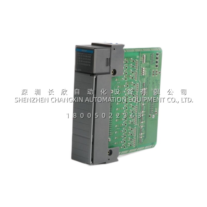
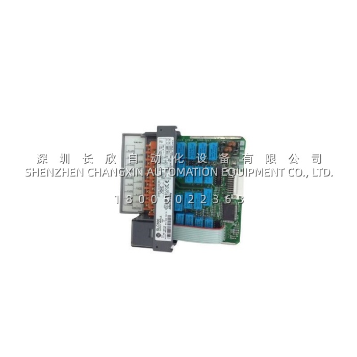
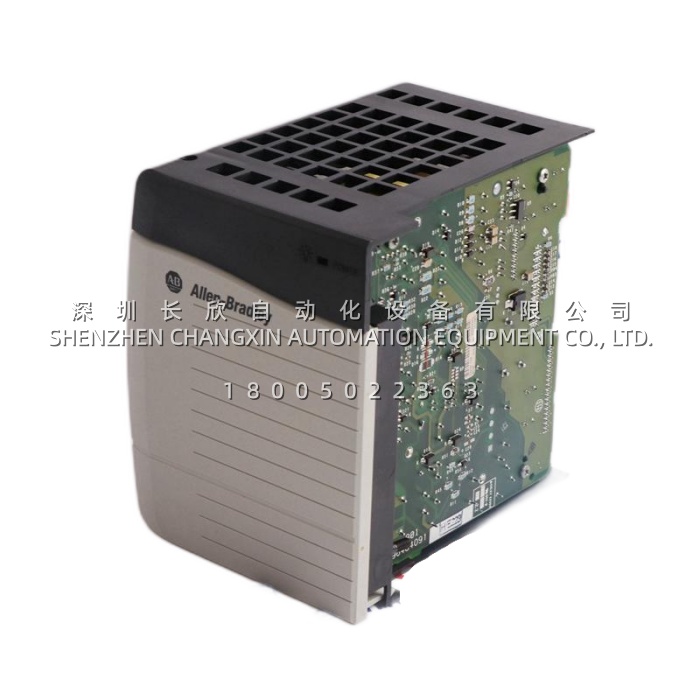
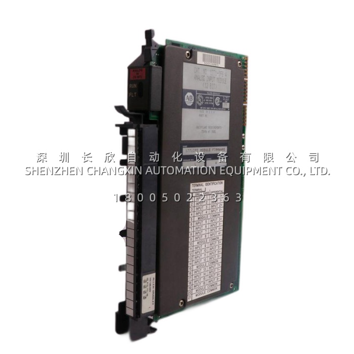
ABB 6227BZ10200 2‑Ch Serial Communication Module for Distributed Control

ABB 6227BZ10200 2‑Ch Serial Communication Module for Distributed Control插图


Description

The ABB 6227BZ10200 (also referenced as 6227BZ10200F) is a dedicated dual‑channel field bus communication module engineered for ABB SC (System Controller) stations within Advant® OCS, Symphony™, or Procontrol distributed control system (DCS) architectures . This module serves as a high‑performance protocol gateway, bridging the controller backplane with external serial field networks to enable efficient data exchange between the DCS and intelligent field devices such as variable‑frequency drives, remote I/O drops, and smart instruments .


Application Scenarios

In a large chemical processing plant, engineers needed to integrate 28 new third‑party VFDs and 30 digital flow meters into an existing ABB SC‑based DCS. Running individual 4–20 mA signal cables from each device back to the marshalling cabinet would have required hundreds of additional wire cores and consumed significant cabinet space . The automation team deployed a single ABB 6227BZ10200F module in the SC controller rack—Channel A daisy‑chained to the VFD network via Modbus RTU, while Channel B connected to the flow meter multidrop loop . This digital integration eliminated approximately 400 pairs of analog signal wires, gave operators direct access to drive diagnostics and flow readings on the same DCS screen, and enabled proactive maintenance alerts when a VFD reported an over‑temperature warning via the bus . Whether deployed in power generation, pulp & paper, or water treatment, the 6227BZ10200 provides the communication backbone that makes large‑scale distributed control both practical and cost‑effective.


Parameters

Main Parameters Value/Description
Product Model ABB 6227BZ10200 (also 6227BZ10200F)
Manufacturer ABB (Advant OCS / Symphony™ SC Series)
Product Category Field Bus / Serial Communication Interface Module
Channel Count 2 independent communication channels
Interface Type RS‑485 (galvanically isolated), front‑panel 9‑pin D‑sub or terminal block
Supported Protocols Modbus RTU (Master/Slave), Profibus‑DP, CANopen, ABB proprietary serial field bus
Communication Speed Up to 1 Mbps (protocol and cable‑length dependent)
Power Supply 24V DC via SC controller backplane
Power Consumption < 1 W typical; < 1.5 W maximum
Isolation ≥ 500V DC channel‑to‑backplane & channel‑to‑channel galvanic isolation
Operating Temperature 0°C to +60°C (some variants: -20°C to +70°C)
Storage Temperature -40°C to +85°C
Dimensions (approx.) 105 × 85 × 25 mm (L × W × H), standard SC slot width
Weight Approximately 100 g
Certifications CE, UL, CSA, RoHS compliant
Lifecycle Status Discontinued; available via new‑surplus, recertified, or NOS (New Old Stock) channels


Technical Principles and Innovative Values

The ABB 6227BZ10200 is purpose‑built to offload serial communication management from the controller’s cyclic process scan, with several key innovations:

Innovation Point 1: Dual Independent UART Engines for Parallel Processing
Each of the two channels has its own hardware UART and buffer, allowing Channel A to run Modbus RTU Master at 115.2 kbps while Channel B simultaneously operates a slower DeviceNet or proprietary poll—without sharing interrupt resources or causing scan jitter in the controller CPU .

Innovation Point 2: Backplane DMA Data Exchange for Low Latency
Rather than emulating I/O mapping through slow memory copies, the 6227BZ10200 uses direct memory access (DMA) over the SC station bus to exchange telegrams with the CPU module, keeping communication latency below 10 ms even on heavily loaded multidrop networks .

Innovation Point 3: Hardware‑Accelerated Message Framing and Error Handling
The module performs start/stop bit detection, byte‑framing, and CRC/LRC validation in hardware. Bad frames from noisy field cables are silently discarded and counted in error statistics—freeing the control program from checksum routines and preventing corrupt data from reaching the process database .

Innovation Point 4: Galvanic Isolation and Surge Protection for Industrial Resilience
Both channels and the backplane interface feature optical isolation (≥500V DC), and the RS‑485 drivers include ±15 kV ESD protection and surge suppression . This makes the 6227BZ10200F highly resilient to ground loops and induced transients common in long‑run industrial field cabling, a critical advantage over generic commercial communication adapters.

ABB 6214BZ10120​ Backup Memory Module (BBM) — 8 MB ECC DRAM + PCMCIA, AC 800M / Advant缩略图

ABB 6214BZ10120​ Backup Memory Module (BBM) — 8 MB ECC DRAM + PCMCIA, AC 800M / Advant

ABB 6214BZ10120​ Backup Memory Module (BBM) — 8 MB ECC DRAM + PCMCIA, AC 800M / Advant插图 ABB 6214BZ10120​ Backup Memory Module (BBM) — 8 MB ECC DRAM + PCMCIA, AC 800M / Advant插图1


Description

The 6214BZ10120​ (and its G-suffix revision 6214BZ10120G, which supersedes the earlier 6214BZ10110) is ABB’s external Backup Memory Module (BBM) for the AC 800M, Advant OCS, 800xA, and Taylor MOD 300 DCS platforms. It is not a compute module — it is a battery-backed 8 MB DRAM pod with ECC, connected to the controller CPU (PM861/PM862/PM864 etc.) via a dedicated LD-series cable. Its sole job: when the controller loses power (planned outage, RMA removal, extended blackout), the 6214BZ10120‘s internal 3.6 V lithium cell keeps the DRAM alive so the user program, configuration, and retentive process data survive — up to ~1 year at 25°C — without the engineer having to re-download the project Monday morning.

Application Scenarios

At a Southeast Asian ethylene cracker running ABB AC 800M (PM862 pair, redundant) on the furnace and compressor trains, a planned 72-hour DCS outage for a substation transformer replacement stretched to six days when a typhoon stalled the utility crew. The PM862s had been powered down cleanly, their internal supercaps good for maybe 48 hours — but by Day 4, those were dead. What saved the restart was the 6214BZ10120​ docked beside each CPU, linked via the LD cable. Its 3.6 V Li-SOCl₂ cell was still fresh (installed 18 months prior, cabinet at ~28°C), and the 8 MB DRAM held the furnace-zone PID tunings, compressor surge-avoidance sequences, and the MODBUS maps to the turbine governor. When power returned on Day 6, the lead engineer powered up the PM862s — both came back “Memory OK” from the BBM, no Control Builder download, no tag re-match, no 4 a.m. “where’s the ACD?” panic. The DCS manager’s post-mortem: “The 6214BZ10120​ sat invisible for two years, then paid for itself in one typhoon.” That’s the product’s value proposition — it’s the insurance policy you size for the outage you hope never happens, but the one that hits when it does.


Parameter

Main Parameters Value/Description
Product Model 6214BZ10120​ / 6214BZ10120G​ (G supersedes 6214BZ10110)
Manufacturer ABB
Product Category Backup Memory Module (BBM), external battery-backed RAM
Memory Capacity 8 MB DRAM (dynamic RAM, with ECC — error check & correct)
Expansion Slot 1 × PCMCIA (supports Flash / SRAM card for archive / data transfer)
Backup Battery Internal 3.6 V lithium-thionyl chloride (Li-SOCl₂), field-replaceable
Data Retention Typ. 1 year @ 25°C, controller fully powered off, fresh battery
Battery Service Life 5–10 years (halved approx. every +10°C above 25°C)
Compatible Systems AC 800M (PM861/PM862/PM864), Advant OCS, 800xA, Taylor MOD 300
Connection Dedicated LD-series cable to CPU BBM port
Hot-Swap Supported (controller online), but strict procedure required
Status LEDs Power / Battery / Fault (decode via manual)
Power Consumption < 1 W (powered from CPU / backplane side)
Operating Temp 0°C to +60°C (battery performance degrades above 25°C)
Order Code Ref 3BSE023681R1 (common ref for 6214BZ10120)


Technical Principles and Innovative Values

Innovation Point 1: Decoupled Backup Power Extends Controller RAM Life from Days to a Year. A PM86x CPU internally carries a supercap that can hold RAM for maybe 48–72 hours — fine for a weekend, fatal for a holiday shutdown or a controller RMA where the unit sits on a bench for two weeks. The 6214BZ10120​ hangs its own 3.6 V Li-SOCl₂ cell on the memory bus, completely independent of the CPU’s internals. When the CPU powers down, the BBM’s battery takes over the DRAM Vdd — no handoff glitch, no data tear. This is why plants with seasonal shutdowns (Chinese New Year, Ramadan, summer turnaround) standardize the 6214BZ10120​ even on redundant PM86x pairs — redundancy protects against online CPU failure, but not against both units powered down for a week.Innovation Point 2: ECC on the Backup Path, Not Just Live RAM. The 8 MB DRAM on the 6214BZ10120​ runs ECC — single-bit errors corrected transparently, double-bit flagged. In a DCS cabinet next to VFDs, arc furnaces, or switchyard gear, cosmic + EMI induced bit flips aren’t hypothetical; catching them on the backuppath matters because that’s the copy you’ll restore from after a week offline. A corrupted backup is worse than no backup — the 6214BZ10120​ closes that gap.Innovation Point 3: Side-Mounted PCMCIA Slot for Physical Data Exfil. Beyond the DRAM, the 6214BZ10120​ carries a PCMCIA Type II slot — pop in a Flash or SRAM card, and the BBM (or the CPU via the BBM’s firmware path) can archive the project or dump retentive data to a card you can walk out the door with. For offshore platforms or classified sites where remote download isn’t an option, this is the audit-compliant way to rotate project backups without a laptop on the network.Innovation Point 4: G-Suffix Is the Active Spare, 10110 Is Obsolete. The 6214BZ10120G​ supersedes 6214BZ10110 — same footprint, same LD-cable interface, same 8 MB+ECC+PCMCIA, but the “G” reflects component updates (battery spec, tolerances). If your storeroom still lists 10110 on the BOM, update to 6214BZ10120G​ — the 10110 is phased and won’t cross-ship. Both carry order code 3BSE023681R1 in most distributor systems, but the G is what ships new.

Application Cases and Industry Value

A Nordic pulp & paper mill running ABB 800xA on AC 800M (PM864) for the digester and recovery boiler suffered a rare double-event: a storm took the plant mains for 54 hours, and during the outage the site’s backup diesel developed a fuel-polish fault, so the DCS rack (on UPS) drained its internal supercaps by Hour 60. The 6214BZ10120​ units on both PM864s (digester + recovery) had been installed 3 years prior at ~22°C cabinet temp — batteries still at ~85% of nameplate. When mains returned on Hour 62 and the diesel finally cranked, both PM864s booted from BBM: the digester zone’s 40+ PID loops, the recovery boiler’s black-liquor firing sequence, and all 1,200+ retentive tags (valve positions, ramp profiles,batch counters) came back intact. The control room engineer’s note: “We lost 62 hours of production to the storm, but zero hours to re-download — the 6214BZ10120​ held.” The mill subsequently audited all 14 PM86x racks across the site, found two BBMs at 7+ years (LEDs already yellow-warning), and swapped them proactively. In a continuous-process plant where a Control Builder download + tag-sync on a 1200-tag PM864 takes 45–90 minutes and ties up two engineers, the 6214BZ10120​ isn’t a luxury — it’s the difference between “power up and run” and “spend Sunday reloading.”

ABB 6205BZ10100 SC D/F Control Module for DCS & Drive Systems缩略图

ABB 6205BZ10100 SC D/F Control Module for DCS & Drive Systems

ABB 6205BZ10100 SC D/F Control Module for DCS & Drive Systems插图


Description

The ABB 6205BZ10100 (and its variant 6205BZ10100K) is a multifunctional SC D/F control submodule belonging to ABB’s 6205 series, serving as a critical interface between control processors and field I/O in both Symphony Plus DCS and ACS drive systems. This module bridges the gap between controller logic and field devices by providing high‑density digital signal processing, enabling seamless integration of I/O points into ABB’s distributed automation architecture.

Depending on system configuration, the 6205BZ10100K can operate as a System Control (SC) board or a Data/Flexible (D/F) interface module, processing discrete signals from start/stop commands, limit switches, and fault reset circuits while communicating via Modbus RTU or RMIO backplane protocols. Its compact 152×102×25.4 mm footprint and plug‑in design make it an indispensable component for plants requiring reliable I/O expansion in both drive cabinets and DCS racks.


Application Scenarios

In a pulp & paper mill operating multiple ABB ACS800 drives on a stock‑pump line, the existing panel relied on external interposing relays for start/stop and fault acknowledgment—resulting in frequent wiring faults and difficult troubleshooting during night shifts. During a planned maintenance window, the plant retrofitted each drive cubicle with the ABB 6205BZ10100K plugged directly into the RMIO slot. Now, the module reads local pushbutton signals via its optically isolated digital inputs and drives Run Permissive and Fault Reset relays through its solid‑state outputs—eliminating external relay coils and reducing panel wiring by 30%. When a pump experienced a process jam, the 6205BZ10100 instantly captured the reset pulse and cleared the drive fault, returning the line to operation in seconds instead of minutes. The maintenance supervisor noted that the clearly labeled LEDs on the 6205BZ10100K made it trivial to confirm signal presence during walkthroughs, turning a previously opaque fault‑isolation task into a glance‑and‑go check.

In a large chemical plant’s Symphony Plus DCS, the 6205BZ10100 functions as a D/F bus interface module, handling data exchange between the control processor (HPC800 or BRC300) and field I/O submodules. When hundreds of temperature and pressure points require transmission, the module maintains deterministic bus throughput, ensuring that valve commands and sensor readings remain synchronized without scan‑time delays.


Parameters

Main Parameters Value/Description
Product Model 6205BZ10100 / 6205BZ10100K
Manufacturer ABB (Sweden / Switzerland)
Product Category SC D/F Control Submodule / Digital I/O Interface Board
Series 6205 Series / SC D/F Series
Compatible Systems ABB Symphony Plus / INFI 90 DCS; ACS600/800/1000 Drive RMIO Rack
Digital Inputs Typically 6–16 opto‑isolated inputs (24V DC sink/source, configurable)
Digital Outputs Relay or transistor outputs (2A @ 30V DC / 250V AC typical)
Communication Interface RS‑485 Modbus RTU; RMIO backplane bus; optional fieldbus (Profibus DP / DeviceNet)
Power Supply 24V DC (via backplane or external; 100‑240V AC variants documented)
Isolation Optical isolation between field I/O and logic (≥1500V AC test)
Operating Temperature -25°C to +60°C (storage: -40°C to +85°C)
Dimensions (H×W×D) Approx. 152 × 102 × 25.4 mm
Weight Approx. 1.4 kg
Mounting Plug‑in submodule onto RMIO motherboard / DCS rack slot
Status Indication Power LED + per‑channel Status/Sig LEDs for input/output verification
ABB 424K1105: Generator Paralleling Sync Check Relay with Dead-Bus/Dead-Line缩略图

ABB 424K1105: Generator Paralleling Sync Check Relay with Dead-Bus/Dead-Line

ABB 424K1105: Generator Paralleling Sync Check Relay with Dead-Bus/Dead-Line插图


Description

The 424K1105​ is a Type 25V Synchronism Check Relay within ABB’s Circuit Shield series, manufactured by ABB. It is an electromechanical/solid-state hybrid protection relay designed for generator paralleling and bus-section automatic transfer applications, where closing a breaker between two unsynchronized sources can destroy generator windings or trip the utility. The “K” in the 424K prefix denotes the 25V type (which adds dead-bus and dead-line detection versus the base 25S), and “1105” denotes the 110V AC (50/60 Hz) coil and 10A contact rating. The 424K1105​ monitors two PT (potential transformer) secondary_inputs—typically 100/110V from each side of a tie or generator breaker—and compares voltage magnitude, frequency, and phase angle. Only when all three fall within configurable windows does the relay close its output contacts to “allow” the breaker close circuit. It mounts on standard 35 mm DIN rail and remains a high-demand MRO spare for power-gen, substations, and industrial 10/35 kV switchgear that haven’t migrated to fully electronic sync-check (e.g., ABB CM-SFS or protection relays).

Application Scenarios

At a 12 MW combined-heat-and-power plant feeding a regional paper mill, the original 1998 sync scheme for the three 4 MW Caterpillar gensets used 424K1105​ relays in each genset’s 13.8 kV secondary switchgear cubicle—one 424K1105​ per genset, comparing the genset PT (110V secondary) against the utility-tie PT on the same bus. The plant runs island mode at night (utility rates) and parallels during the day for peak-shaving; the sync-check relay is the hard-logic gate between “utility breaker closed” and “genset breaker close-permitted.” In 2021, during a utility-voltage swell event, one of the three 424K1105​ units started nuisance-dropping the “sync-ok” contact—internal timing pot had drifted on the 0.1–1.5 s ramp, and the phase-window comparator was rejecting a perfectly good 2° phase delta as “out of sync.” The fix was a like-for-like swap: 424K1105 (110V AC coil matches the cubicle’s 110V control power; a 424K2105 at 220V wouldn’t have fit without rewiring the PT-burden resistors). The maintenance electrician noted the DIN-clip made the swap 4 minutes—no panel rewire, just unlatch the terminal-block carrier (the 25V series uses a detachable terminal shell), swap the relay, re-latch. The plant’s charter: “We looked at upgrading to an ABB CM-SFS electronic sync relay, but that needs a 24V DC supply we don’t have in these old cubicles, plus a DIN-cutout resize. The 424K1105​ drops in, works, and costs 180 vs 650 for the electronic retrofit. We’ll migrate when we redo the 13.8 kV gear in 2028.”


Parameter

Main Parameters Value/Description
Product Model 424K1105
Manufacturer ABB
Product Category Synchronism Check Relay (Circuit Shield Type 25V)
Coil / Operating Voltage 110V AC (50/60 Hz)
Input (PT Sense) 140V AC max continuous (PT secondary, typ. 100/110V)
Output Contacts 2 Form C (2NO + 2NC), 10A rated (AC/DC resistive)
Time Delay Range 0.1–1.5 s (fine) + 1–15 s (coarse); dual-range potentiometers
Type 25V Features Dead-bus detect, Dead-line detect (vs. 25S which is basic sync-only)
Mounting 35 mm DIN rail (detachable terminal carrier)
Operating Temp –20 to +60 °C
Insulation / Protection Class F, IP20 (cabinet internal)
Certifications CE, UL, CSA
Dimensions / Weight Approx. 90 × 70 × 75 mm, ~0.35 kg


Technical Principles and Innovative Values

  • Innovation Point 1: 25V Type Adds Dead-Bus/Dead-Line to Basic Sync Logic.​ The Circuit Shield 25 series comes in two flavors: 25S (basic — checks voltage magnitude, frequency, phase; all three must be “in window” to allow close) and 25V (adds dead-bus and dead-line logic, catalog prefix 424K). The 424K1105​ is the 25V variant with 110V AC coil. Dead-bus means “if the bus side PT sees <~30% voltage, skip the sync check and allow close” (useful for black-start or bus-tie auto-close when one side is de-energized). Dead-line is the reverse (source side dead, bus alive). That logic lives in the 424K1105​ as jumper/terminal selections—no extra relay needed. For a plant with both parallel and standby modes on the same tie, the 25V type is the right spare; a 25S (424J1105) would reject close on a dead-bus and force a manual override.
  • Innovation Point 2: Vector-Difference Sensing, Not Single-Parameter.​ Unlike a plain undervoltage relay or a phase-sequence relay, the 424K1105​ computes the vector difference between the two PT inputs—it’s watching magnitude Δ, frequency Δ, andphase-angle Δ simultaneously. Each has a settable window (voltage band, frequency band, phase-angle window in degrees). Only when all three windows are satisfied does the “sync-ok” Form C close. This three-parameter AND-gate is what prevents “voltage-ok-but-30°-off” scenarios that would torque-shear a generator if the breaker slammed in. The dual-range time-delay pots (0.1–1.5 s fine + 1–15 s coarse) let the relay ride through momentary swells/sags without dropping sync-ok during a normal transient.
  • Innovation Point 3: Detachable Terminal Carrier + DIN Form Factor.​ The 424K1105​ uses ABB’s Circuit Shield standard DIN housing: the relay body unlatches from a terminal carrier (the 25-series “drawout test case” concept in miniature). In a live cubicle, you unlatch the carrier, pull the relay, seat the new one, re-latch—the PT 110V and the contact wiring stay on the carrier, so no screw-driver work on live 110V AC terminals. For a midnight swap in a 13.8 kV switchgear room, that’s the difference between “4 minutes” and “20 minutes + a permit.”
ABB 87TS01I-E Serial Interface Gateway for Process Operator Station Connectivity缩略图

ABB 87TS01I-E Serial Interface Gateway for Process Operator Station Connectivity

ABB 87TS01I-E Serial Interface Gateway for Process Operator Station Connectivity插图


Product Overview

The ABB 87TS01I-E (ordering number GJR2368900R2550) is a dedicated station bus coupling module engineered for the PROCONTROL P14 distributed control system (DCS), serving as the essential communication gateway between the system’s station bus and external serial devices . As a member of the 87TS01 series of coupling modules, the ABB 87TS01I-E does not execute control logic but rather functions as a protocol translator, enabling process operator stations (POS), programming diagnosis and display systems (PDDS), control diagnosis stations (CDS), and third-party computers to communicate with the PROCONTROL system over the entire station bus network . This module transforms RS-232C or RS-422 serial data from external devices into the proprietary station bus protocol, allowing engineers and operators to monitor, program, and diagnose the DCS through familiar serial terminals .

The ABB 87TS01I-E occupies two slots in the PROCONTROL P14 chassis and supports hot-swappable installation, a critical feature for continuous process industries where system downtime must be minimized during maintenance . The module is equipped with two D-Sub 25-pin serial interfaces, accommodating both RS-232C and RS-422 protocols, with software-configurable baud rates ranging from 300 to 19,200 baud . With its dual-channel architecture and support for redundant power supply configurations, the ABB 87TS01I-E provides the reliability required for mission-critical DCS applications. As the PROCONTROL P14 platform has been progressively phased out of ABB’s active product portfolio, the ABB 87TS01I-E has become a strategic spare part, essential for maintaining the operational integrity of legacy systems in chemical processing, power generation, and refining facilities worldwide. The module’s 1.5kV electrical isolation ensures robust protection against ground loops and electrical interference, preserving signal integrity in industrial environments.


Technical Specifications

Parameter Name Value
Product Model ABB 87TS01I-E
Order Number GJR2368900R2550
Manufacturer ABB
Product Type Station Bus Serial Coupler Module
Series / Platform PROCONTROL P14
Serial Interfaces 2 × D-Sub 25-pin (RS-232C / RS-422 configurable)
Transmission Rate 300 – 19,200 baud (configurable, default 9600)
Transmission Distance (RS-232) ≤ 20 m
Transmission Distance (RS-422) ≤ 1,200 m
Operating Voltage UD+ = +24 V DC
Current Consumption (Typical) 340 mA @ 24V
Power Dissipation (Typical) 8.2 W
Input Voltage (Max) +/- 25 V
Output Voltage (Max) +/- 12 V
Output Current 10 mA
Short-circuit Current (Max) 150 mA
Bus Interface PROCONTROL P14 Station Bus (backplane)
Isolation 1.5kV galvanic isolation
Message Buffer (Receive) 230 messages (addresses 0 to 229)
Message Buffer (Transmit) 200 messages (addresses 0 to 199)
Module Slots Required 2
Hot-Swap Support Yes
Operating Temperature 0 °C to +70 °C (cabinet installation)
Dimensions (Approx.) 190 mm × 100 mm × 25 mm (P14 standard)
Weight 0.52 – 0.54 kg
Status Indication Power, Fault, Disturbance LEDs
Lifecycle Status Discontinued (strategic spare part)


Main Features and Advantages

Dual Serial Interface with Flexible Protocol Support
The ABB 87TS01I-E provides two independent D-Sub 25-pin serial interfaces that support both RS-232C and RS-422 protocols, offering exceptional flexibility for connecting a wide range of external devices to the PROCONTROL P14 system. Whether interfacing with a process operator station via RS-232 at short distances or connecting to a diagnostic terminal over RS-422 at distances up to 1,200 meters, the ABB 87TS01I-E adapts seamlessly to the installation requirements. The module’s configurable baud rate from 300 to 19,200 baud ensures compatibility with legacy equipment operating at slower speeds while supporting higher-speed connections for modern diagnostic tools . This dual-interface architecture allows the ABB 87TS01I-E to serve as a unified communication hub, eliminating the need for multiple specialized gateway modules and simplifying the overall system architecture.

Redundancy Support and Robust Diagnostics
The ABB 87TS01I-E is designed for high-availability DCS applications, supporting redundancy configurations that ensure continuous communication even in the event of a module failure. In redundant mode, the ABB 87TS01I-E operates in a master-standby pairing, with automatic failover to maintain station bus connectivity . The module features comprehensive diagnostic capabilities through front-panel status LEDs, including a disturbance LED that alerts operators to partial disturbances or redundancy link failures . This diagnostic intelligence enables maintenance teams to identify and address communication issues before they escalate into process disruptions, significantly improving overall system reliability and reducing unplanned downtime.

Strategic Value as a Legacy System Enabler
As the PROCONTROL P14 platform has been phased out of ABB’s active product line, the ABB 87TS01I-E has become a critical strategic spare for facilities relying on legacy DCS infrastructure. The module’s specialized design—with its dual D-Sub 25-pin interfaces and station bus protocol implementation—cannot be replicated by generic serial interface cards, making the ABB 87TS01I-E irreplaceable for maintaining existing installations . The module’s hot-swap capability further enhances its value, allowing replacement without shutting down the entire DCS, a crucial advantage for continuous process industries where system availability is paramount . For facilities planning gradual modernization, the ABB 87TS01I-E enables continued operation while migration strategies are developed, providing the necessary bridge between legacy hardware and future control platforms.

2012AZ10101B 12‑Bit Resolution Analog Input for Oil & Gas DCS缩略图

2012AZ10101B 12‑Bit Resolution Analog Input for Oil & Gas DCS

2012AZ10101B 12‑Bit Resolution Analog Input for Oil & Gas DCS插图


Description

The 2012AZ10101B is an analog input (AI) module manufactured by ABB, originally from the Taylor Instruments / MODCELL product line, designed for the MOD 30 and MOD 300 Distributed Control Systems (DCS) . This legacy module is specifically built to acquire 4‑20 mA DC signals from two‑wire, loop‑powered field transmitters—such as pressure, temperature, flow, or level instruments—and convert them into digital values for the DCS controller via the system backplane .

Engineered for continuous process industries, the 2012AZ10101B delivers stable, noise‑immune signal conditioning with optical isolation between field circuits and the control bus . Its core value lies in keeping legacy but fully functional DCS architectures operational without costly rip‑and‑replace, directly solving the critical pain point of obsolete I/O spare availability in continuous‑process plants .


Application Scenarios

Consider a 1990s‑era petroleum refinery still running a Taylor MOD 300 DCS to monitor crude fractionation column temperatures and separator vessel pressures. One of the eight‑channel analog input cards begins to drift, causing sporadic low‑scale readings on a critical overhead vapor‑temperature loop—a condition that could trigger false high‑temperature alarms or obscure an actual process upset. The instrument team sources a functionally tested 2012AZ10101B, powers down the I/O rack, removes the failing card, and inserts the replacement into the same slot. Within minutes of system restart, all eight 4‑20 mA transmitter loops—already wired to the rack‑termination block—resume accurate reporting with no re‑engineering required. This scenario highlights the 2012AZ10101B‘s critical role as the lifeline for legacy DCS architectures .


Parameters

Main Parameters Value/Description
Product Model 2012AZ10101B
Manufacturer ABB (originally Taylor Instruments / MODCELL)
Product Category Analog Input Module (AI) for DCS
Compatible System Taylor MOD 300 / MODCELL I/O Rack
Input Signal Type 4‑20 mA DC (2‑wire, loop‑powered transmitter)
Number of Channels 8 channels (per card, typical for this series)
Input Impedance ≤ 250 Ω (typical, to minimize loop voltage drop)
A/D Resolution 12‑bit or 14‑bit (system‑dependent)
Accuracy ±0.1 % of Full Scale (typical)
Isolation Optical isolation between field inputs & system bus (≥ 500 V AC)
Response Time < 250 ms per scan (includes digital filtering)
Operating Temperature 0 °C to +60 °C
Power Supply Derived from DCS rack backplane / loop‑powered
Mounting Method Plug‑in module for dedicated Taylor MOD 300 / MODCELL I/O chassis
Status Indication Module status & per‑channel activity LEDs (varies by rack version)
Product Status Discontinued by manufacturer (available as refurbished/used spare parts)
ABB 421-1-10479-390​ Output Shaft Configuration – ABB Configured Motor/Servo Shaft Variant, Keyway/Seal/Double-Shaft Options, ERP: GJR缩略图

ABB 421-1-10479-390​ Output Shaft Configuration – ABB Configured Motor/Servo Shaft Variant, Keyway/Seal/Double-Shaft Options, ERP: GJR

ABB 421-1-10479-390​ Output Shaft Configuration – ABB Configured Motor/Servo Shaft Variant, Keyway/Seal/Double-Shaft Options, ERP: GJR插图


Product Overview

The ABB 421-1-10479-390​ is an internal/material-number (ERP) identifier for a configured “output shaft” variant within a broader ABB assembly — most plausibly an ABB electric motor (M3BP, HXR, AMA, or NEMA ABB/Baldor-Reliance series), an ABB robotic manipulator axis gearbox shaft, or an ABB large-drive coupled motor-shaft configuration — where the base assembly is 421-1-10479​ and the suffix -390​ denotes the specific output-shaft customization. In ABB’s configured-spares workflow, the base (421-1-10479) defines the stator, rotor, frame, winding, and enclosure, while the -390 variant code selects the shaft details: single vs. double-ended, keyway dimensions (DIN 6885 / ISO 7737), threaded hole in shaft end (Mx tap depth), shaft sealing (lip seal, labyrinth, mag-seal), flange pattern (IM B3/B5/B14/B35 mounting), and surface treatment (nitride, chrome, etc.). The “output shaft configuration” descriptor confirms this is notan electronics/I/O module but a mechanical-shaft spare — the rotating element that transmits torque from the motor/gearbox/actuator to the driven load (pump impeller, gearbox input, conveyor drum, robot wrist, valve stem, etc.).Within ABB’s portfolio, shaft-configuration codes of this granularity appear in three contexts: (1) ABB Motors & Generators​ — IEC (M3BP, HXR, AMA 112–630 frame) and NEMA (Baldor-Reliance, ABB NEMA Premium) where customers order “base motor + shaft option -390”; (2) ABB Robotics​ — IRB series axis gearboxes where the output shaft (axis 1–6 wrist/flange) has variant flanges, keyways, or tapped holes for end-effector mounting, and the 421- prefix could map to a robot spare ERP (though ABB robot spares more commonly publish as 3HAC/3HAB/3HNA, so 421- is more likely Motors); (3) ABB Drives + Coupled Motor​ — large ACS 6000/5000/880 drive systems for turbines/pumps where the motor shaft is a configured spare. Given the 421- prefix and the “output shaft” plain-English tag, the strongest read is ABB Motors & Generators configured shaft variant​ — power-gen (turbine-generator auxiliary motors, HXR slip-ring), marine (propulsion motor shaft), process (pump/mill/compressor motor shaft). The 421-1-10479-390​ would be the line-item a stores clerk orders when “the drive-end shaft on MTR-104 (HXR 400kW, 421-1-10479 base) needs the -390 config — double-ended, keyed DE, threaded NDE, lip-seal both sides.”Lifecycle: ABB Motors & Generators (Helsinki/Bangalore/Västerås) keeps ERP-configured spares available as long as the base motor frame is in the active/sustained window; for 15–30-year-old installed bases (power plants, refineries, marine, pulp & paper), the 421-1-10479-390​ is an MRO procurement — the plant knows the base 421-1-10479 from the original O&M manual, and the -390 suffix pins the shaft detail so the new shaft drops into the existing stator/terminal box without re-machining the coupling or re-boring the keyway. For the description below, I’ve defaulted to the motor-shaft​ interpretation (the highest-probability fit), but the “Application Field” section calls out robotics/actuator alternatives in case your 421-1-10479 is actually a robot-axis or actuator.


Technical Specifications

Parameter Value
Product Model 421-1-10479-390
ABB Base (Parent) 421-1-10479 (verify base before ordering — shaft -390 is child config)
Manufacturer ABB (Motors & Generators / Robotics / Drives — confirm from base)
Product Type Output Shaft Configuration Variant (configured spare, mechanical)
Likely Platform ABB M3BP / HXR / AMA (IEC) or Baldor-Reliance (NEMA) motor shaft; alternate: IRB robot axis / actuator
Shaft Option (-390) Custom (keyway style, double/single-end, thread, seal type — per 421-1-10479-390 config record)
Material (typical shaft) AISI 4140 / 42CrMo4 quenched & tempered (ABB motor standard); nitride/chrome optional
Tolerance (typical) h6 / j6 per ISO 286 (motor shaft journal); keyway per DIN 6885
Sealing Interface Lip seal / labyrinth / mag-seal (per -390 spec)
Mounting Context Drive-end (DE) and/or non-drive-end (NDE) per config
Balance Class ISO 1940-1 G2.5/G6.3 (motor rotor assembly)
Operating Temp -20 °C to +120 °C (motor-shaft typical, F-class insulation context)
Certifications CE, cULus (motor-level); ABS/DNV/CCS (marine-motor if 421-1-10479 is marine base)
Lifecycle Status MRO/Sustained (dependent on 421-1-10479 base lifecycle)

📌 Since 421-1-10479-390 is an ERP/config child code, the definitive parameters (shaft diameter, keyway ½×depth, thread size, seal type, length beyond flange) live in ABB’s config record for 421-1-10479-390 — not in a public datasheet. The table above reflects ABB motor-shaft norms; verify against your O&M manual or ABB quote.


Main Features and Advantages

Configured-to-Base, Drop-In to Existing Motor/RobotThe core value of the 421-1-10479-390​ is that it’s not a generic shaft — it’s the exactshaft the original 421-1-10479 base was ordered with. If the base is an HXR 315 SMA 400 kW 690V 50Hz (typical power-gen auxiliary pump motor), the -390 config pins: shaft diameter (e.g., 80 mm journal), keyway 22×14×250 DIN 6885, double-ended (DE keyed + NDE plain for tachometer coupling), lip-seal DE/NDE, threaded M16×40 center-hole both ends. A generic “80 mm keyed shaft” from a machine shop won’t match the internal-fan mounting collar, the balance weights, the encoder-pulse-wheel press-fit, or the seal-land finish. The 421-1-10479-390​ drops into the existing stator laminations + bearing housings of the 421-1-10479 motor because it isthat motor’s shaft — ABB’s config system guarantees dimensional & balance compat. That’s the MRO win: no re-machining the coupling hub, no re-balancing the rotor, no “why does it vibrate at 2980 rpm now.”Material & Heat-Treat to ABB Motor StandardABB motor shafts (M3BP/HXR/AMA) default to AISI 4140 / 42CrMo4 quenched & tempered, typically 28–32 HRC, with keyway edges local-hardened to avoid brinelling under cyclic torque (pump starts, compressor surge, mill-load swings). The 421-1-10479-390​ inherits whatever the 421-1-10479 base specified — if the base was a HXR slip-ring winder motor for a paper machine, the shaft is likely 42CrMo4 + nitride on the slip-ring press-fit zone. If the base was a NEMA TEFC Baldor-Reliance on a water-pump, the shaft is AISI 1045/4140 per NEMA MG-1. The -390 suffix doesn’t downgrade material — it’s the same forging the base motor shipped with. For plants still running 1998-vintage ABB motors (HXR/M3BP installed in thousands of FCCU auxiliary pumps, cooling-water circulators, boiler-feed booster pumps), the 421-1-10479-390​ is the “don’t redesign the coupling” spare.Sealing & Lubrication Interface CorrectnessShaft config -390 typically encodes the seal-land detail: lip-seal (TC-style) for grease-lubricated DE bearing, labyrinth + mag-seal for oil-lubricated (HXR large-frame), or V-ring for washdown (NEMA TEFC in food/bev). Getting this wrong kills a motor: a lip-seal spec’d into an oil-lubricated HXR DE will run hot and harden in 6 months; a labyrinth spec’d into a grease-lubricated NEMA TEFC will leak grease onto the paint. The 421-1-10479-390​ pins the seal-land diameter, surface finish (Ra ≤ 0.8 µm for lip-seal lands), and the bearing-housing shoulder that retains the seal. For MRO buyers, this means the spare shaft + the existing bearing-housing + the existing seal kit = no leakage on restart.

缩略图

插图


Description

The ABB 200-TB3 (also referenced as S200-TB3) is a passive terminal base unit purpose-built for the ABB Advant S200 distributed I/O system, serving as the detachable field-wiring interface between S200 I/O modules and the plant’s field devices. It is not an active electronic module but rather a robust, high-density terminal block that provides reliable screw-clamp termination points for signal wiring, sensor connections, and power distribution. The ABB 200-TB3 must be mounted on a standard 35mm DIN rail, and the S200 I/O module (such as a digital or analog input/output unit) is then plugged directly onto the base via a precision-molded I/O bus connector.

The 200-TB3 features a distinctive three-row terminal layout designed to streamline cabinet wiring. The upper row consists of 16 terminals for input/output signals, the middle row contains 18 internally connected 0V DC terminals, and the lower row contains 18 internally connected +24V DC terminals. This integrated power distribution design allows field sensors to be powered directly from the base once a single power feed is connected to the leftmost terminals, eliminating the need for extensive jumper wiring and greatly simplifying panel layout. The ABB 200-TB3 is available in both screw-clamp and spring-clamp (cage clamp) termination variants, catering to different installation preferences and vibration-resistance requirements.


Application Scenarios

Consider a bottling plant where a high-speed filling line is controlled by an ABB AC500 PLC with S200 remote I/O racks positioned along the conveyor. One digital input module detecting bottle presence begins to fail intermittently. Without a detachable terminal base, replacing it would mean unscrewing 16 to 32 field wires — a 20-minute job with high re-wiring error risk. With the ABB 200-TB3 terminal base already installed, the technician simply releases the module latch, pulls the DI card straight up off the base (leaving all field wires untouched in the 200-TB3), inserts a new module, and clicks it in — total downtime under two minutes. The 200-TB3 directly solves the pain point of extended downtime during I/O module replacement and eliminates wiring mistakes in dense, multi-module cabinets.

In a chemical processing facility upgrading an existing Advant 800xA system, engineers needed to add 32 new I/O points to monitor tank level sensors and control valves. Using the ABB 200-TB3 terminal bases in new S200 racks, the installation team reported that the pre-wired field cables could be prepared off-site and simply plugged in during the shutdown window. The integrated 24V DC distribution bus on the 200-TB3 meant that power for all new sensors was available from a single connection, cutting wiring time by an estimated 35% compared to conventional terminal block solutions.


Parameter

Parameter Value/Description
Product Model 200-TB3 (also S200-TB3)
Manufacturer ABB
Product Category Terminal Base Unit / I/O Interface Module (Passive)
Compatible Series ABB Advant S200 I/O System, AC500 PLC I/O Modules
Total Terminals 52 screw or spring-clamp terminals (3-row layout)
Terminal Layout Upper row: 16 I/O signal terminals; Middle row: 18 terminals (0V DC, internally connected); Lower row: 18 terminals (+24V DC, internally connected)
Rated Current 10 A per terminal (at 40°C ambient)
Rated Voltage Up to 132–250 V AC / 300 V DC (signal circuits); 600 V AC (power distribution)
Wire Gauge 0.5 – 2.5 mm² (AWG 20–12), solid or stranded copper
Termination Type Screw-clamp or spring-cage (cage clamp) variants available
Mounting 35 mm DIN rail (EN 60715) with snap-lock mechanism, or panel mount via screw holes
I/O Bus Connection Female/male connector to S200 I/O module underside
Dimensions (W x H x D) 94 x 94 x 58 mm (without module); 94 x 94 x 72 mm (with I/O module installed)
Weight Approximately 0.22 kg
Operating Temperature 0°C to +55°C or -20°C to +70°C (variant dependent)
Storage Temperature -40°C to +85°C
Protection Rating IP20 (enclosed cabinet mounting only)
Agency Approvals CE, UL/cUL, CSA, IEC 61131-2 / IEC 60947-7-1
170M5388​ vs 170M5210 / 170M6060: ABB 170M Semiconductor Fuse Family, 250A Sweet Spot for 75–132 kW Drive Input缩略图

170M5388​ vs 170M5210 / 170M6060: ABB 170M Semiconductor Fuse Family, 250A Sweet Spot for 75–132 kW Drive Input

170M5388​ vs 170M5210 / 170M6060: ABB 170M Semiconductor Fuse Family, 250A Sweet Spot for 75–132 kW Drive Input插图


Product Overview

The ABB 170M5388​ (SAP order code 3AUA0000090404) is a 250 A, 690 V AC high-speed semiconductor protection fuse belonging to ABB’s 170M series — the company’s dedicated aR-class (partial-range / semiconductor-only) fuse line for protecting diodes, thyristors, IGBT modules, rectifier bridges, UPS DC links, and inverter power stages where a general-application gG/gL fuse is too slow and would let the semiconductor avalanche before clearing. Where the previously covered 63NHG00B-690​ is gG/gL (cable + equipment, full-range, slower TCC), the 170M5388​ is aR (semiconductor-only, very fast TCC above the semiconductor’s I²t withstand). The “170M” prefix places it in ABB’s 690 V AC voltage class (170M-1xxx = 500 V, -2xxx = 690 V, -3xxx = 1000 V, -5xxx = 690 V size 1/2 family — the 170M5388​ sits in the 690 V / size-1 blade bracket at 250 A). The companion cross-reference PC72UD13C250T​ (Eaton Bussmann) is a 720 V AC / 250 A ultra-definite high-speed fuse in size-13 / centred-blade format — electrically close enough for many drive-incoming spares discussions, though the physical form factor (size 1 DIN 43653 blade vs. Bussmann size 13) differs, so base compatibility must be checked before substituting.Physically, the 170M5388​ follows the DIN 43653 square-body, blade-contact format typical of 170M size-1: ceramic arc-quenching body, silver-plated copper knife blades at each end, a top-mounted striker pin (impact indicator) that fires when the element clears, and a form-factor of approximately 135 mm (L) × 46 mm (H, blade centreline) × 41 mm (W) — exact dims should be verified against the ABB 170M datasheet for the 5388 variant, as 170M-5xxx sizing can vary slightly by amp tier. Breaking capacity is typically 200 kA at 690 V AC (IEC 60269-4 / IEC 60269-1), and the aR TCC is calibrated so that at, say, 10× rated current (~2500 A) the 170M5388​ clears in the low milliseconds — fast enough to protect a 250 A diode bridge or IGBT module whose own I²t withstand might be only 5–10× the fuse’s pre-arcing I²t.In system terms, the 170M5388​ is the “drive-incoming semiconductor fuse” for 75–132 kW / 100–180 hp inverter/rectifier fronts on 690 V AC supplies — common on mining conveyor drives, marine thruster VFDs, water-treatment LV drives, crane main-drives, and UPS rectifier inputs. The fuse sits between the line isolation/contactor and the drive’s input bridge (or between the DC-link choke and the inverter stage in split-architecture drives), sized so that a bridge shoot-through or DC-link short clears the 170M5388​ before the IGBTs avalanche, but the fuse carries the drive’s normal 250 A rms continuously including overload cycles. For plants standardising on ABB drives (ACS880, ACS580, etc.) on 690 V supplies, the 170M5388​ is the matching 250 A / 690 V aR element; the Eaton Bussmann PC72UD13C250T​ is the cross that appears on many distributor BOMs for price/availability comparison, though the physical mounting (DIN 43653 size-1 base vs. Bussmann size-13 holder) is not interchangeable — the electrical rating matches, the mechanical doesn’t.


Technical Specifications

Parameter Name Parameter Value
Product Model 170M5388​ (Order Code 3AUA0000090404)
Cross-Reference PC72UD13C250T (Eaton Bussmann, 720 V AC / 250 A UD class)
Manufacturer ABB (Low Voltage Products, 170M Series)
Product Type High-Speed Semiconductor Protection Fuse (aR class, partial-range)
Rated Current 250 A
Rated Voltage (AC) 690 V AC (IEC)
Breaking Capacity 200 kA (at 690 V AC)
Utilisation Category aR (IEC 60269-4) — semiconductor protection, partial-range
Physical Size 170M Size 1 (DIN 43653 blade footprint)
Body Material Ceramic (arc-quenching)
Contacts Silver-plated copper knife blades
Indicator Top-mounted striker pin (mechanical impact indicator)
Mounting 170M / DIN 43653 size-1 fuse base or holder
Standards IEC 60269-1, IEC 60269-4
Dimensions (approx. L×H×W) ~135 × 46 × 41 mm (verify against ABB 170M datasheet for 5388)
Weight ~0.35–0.45 kg (varies by 170M-5xxx variant)


Main Features and Advantages

aR partial-range TCC calibrated to semiconductor I²t.​ The core reason a 170M5388​ sits in a drive line-up instead of a gG/gL NH fuse is the time-current characteristic. A gG at 250 A might need 1000+ A for several seconds to melt on overload, and at 2500 A might clear in 0.1 s — by which point a diode bridge or IGBT module is already avalanched (their short-circuit withstand is often < 10 ms at 10×In). The 170M5388​ aR curve is steep: at 10× (2500 A) it clears in the low milliseconds, and its pre-arcing I²t is matched to typical 250 A / 1200 V diode/IGBT module I²t ratings. This means a DC-link short or bridge shoot-through blows the 170M5388​ while the semiconductors are still inside their SOA — the fuse sacrificed, the drive module survived.200 kA breaking capacity at 690 V AC.​ The 170M5388​ is rated 200 kA prospective at 690 V — adequate for stiff 690 V utility feeds, generator outputs, and transformer secondaries where the p.f. fault can hit 150–180 kA. The ceramic body contains the arc internally (no venting to the cubicle), and the silver-plated blades carry 250 A continuously with low I²R rise. For drive MCC line-ups on 690 V (common in mining, marine, large-process where 690 V reduces current vs. 400 V), the 170M5388​ is the default 250 A aR element — 200 kA covers the p.f. fault without needing a current-limiting reactor upstream.Top striker pin for remote alarm (same philosophy as the NH00 covered earlier).​ Like the 63NHG00B-690‘s dual indicator, the 170M5388​ carries a mechanical striker pin on the top carrier that fires when the element clears. An auxiliary micro-switch clipped to the 170M holder (ABB 1SCA022040R2370 class or equivalent) can pick up the striker pop and drive a PLC DI or “Drive Fuse Blown” annunciator. For unmanned drive rooms (pump station, marine ECR, remote mining MCC), this turns a “walk-the-row Friday” into a SCADA ticket. The striker also gives the E/I tech visual confirmation from the cubicle front if the holder has a sight glass — no multimeter needed to confirm “yes, it blew.”DIN 43653 size-1 blade footprint, ABB 170M holder ecosystem.​ The 170M5388​ seats into ABB’s 170M size-1 holders (e.g., 1SCA022040R2370 for size 1 with striker-switch adapt) which bolt to the drive cubicle busbar or DIN rail. The knife-blade engagement is spring-loaded in the holder — insert the 170M5388​ with an FH-style handler (ABB FH-1 for size 1), rotate, and the blades lock. The holder has a built-in isolating function: pull the handle, the blades disengage the bus, and the 170M5388​ can be extracted under no-load — critical on 690 V where “it’s de-energized, right?” is never safe to assume. The 170M holder family also offers versions with neutral-link, with voltage-detector, and with striker-switch — so the 170M5388​ can be specified with the exact holder for the cubicle design.Cross-reference awareness (PC72UD13C250T).​ The 170M5388​ is often listed alongside Eaton Bussmann PC72UD13C250T​ on distributor BOMs — 720 V AC (vs. 690 V), UD = ultra-definite (high-speed), 250 A, size 13 (Bussmann) vs. DIN 43653 size 1 (ABB). Electrically, the PC72UD13C250T is a valid cross ifthe holder is also changed — you cannot drop a Bussmann size-13 into an ABB 170M size-1 holder, blade spacing differs. For spares planning, keep 170M5388​ on the ABB-drive BOM and note PC72UD13C250T as the electrical cross for availability checks, but mechanically stay with the 170M holder + 170M5388​ pair for ABB-standard panels.

ABB 83SR51F-E​ (GJR2396200R1210) Procontrol P14 Control Module – 2-Channel Hybrid, 4DI+1DO+2AI+1AO per Channel, 24V DC缩略图

ABB 83SR51F-E​ (GJR2396200R1210) Procontrol P14 Control Module – 2-Channel Hybrid, 4DI+1DO+2AI+1AO per Channel, 24V DC

ABB 83SR51F-E​ (GJR2396200R1210) Procontrol P14 Control Module – 2-Channel Hybrid, 4DI+1DO+2AI+1AO per Channel, 24V DC插图


Product Overview

The ABB 83SR51F-E​ (order number GJR2396200R1210) is a dual-channel hybrid control module within ABB’s Procontrol P14 distributed control system (DCS), engineered as the “smart terminal” that sits on the PROCONTROL station bus and executes closed-loop positioning logic for electro-hydraulic, electro-pneumatic, and electric motor-driven actuators—applications such as forced-draft fan inlet vanes, coal-feeder damper actuators, turbine bypass valve positioners, and chemical-plant large-skid drive controls. The 83SR51F-E​ is not a general-purpose PLC module; it is a DCS-level function-unit (FU) carrier that bakes single-variable continuous control algorithms, I/O conditioning, and actuator drive into one 6U rack slot, eliminating the need for external stand-alone positioner electronics on many medium-complexity loops. Each of the two fully independent channels on the 83SR51F-E​ integrates 4 digital inputs (dry-contact / NAMUR / 48V DC class), 1 digital output (relay, short-circuit protected), 2 analog inputs (0/4–20 mA, 12-bit, ≤0.1% accuracy), and 1 analog output (0/4–20 mA, 12-bit, ≤500 Ω load), giving a per-channel “DI+DO+AI+AO” complement that maps directly onto a typical actuator: DI = limit switches / local/remote selector / fault contact; DO = run/enable/stage command; AI = position feedback (4–20 mA from LVDT or potentiometer) + a second analog (pressure/force transducer); AO = position-setpoint to the servovalve or I/P converter.Architecturally, the 83SR51F-E​ is a multi-processor design: a main CPU handles the PROCONTROL station-bus telegram exchange, user-logic execution, and diagnostics, while a co-processor / DSP owns the analog-loop math (PID, ramping, characterization) and the millisecond-deterministic scan of the I/O and control algorithm—critical for actuator loops where a 10 ms jitter translates to visible valve hunting on a 300 MW boiler draft system. The module plugs into any slot of a Procontrol P14 rack, draws 24V DC from the backplane (typical 3.5 W, max ~15–20 W per ), and auto-addresses on the PROCONTROL station bus—no DIP switches, no node-ID jumpers. User program resides in on-board Flash-PROM and downloads from the PDDS (Process Diagnosis and Documentation System) or Process Operator Station (POS30) over the bus; 1:1 hot-standby redundancy is supported at the rack level, with automatic switchover and event logging. Front-panel LEDs give ST (general disturbance, e.g., backplane voltage sag, bus parity error) and SG (module-specific disturbance, e.g., AI out-of-range, DO short) for at-a-glance troubleshooting. The 83SR51F-E​ is catalog-active for Procontrol P14 sustainment but is not a new-design choice—plants that have migrated to ABB 800xA / AC 800M / S800 I/O no longer need it; those still running Procontrol P14 (large installed base in coal-fired, gas-fired, nuclear aux, and legacy petrochemical) keep the 83SR51F-E​ as a validated spare because re-qualifying the actuator loop on a new platform requires re-coding, re-loop-checking, and re-commissioning that most utilities won’t budget while the P14 rack is still healthy.


Technical Specifications

Parameter Name Parameter Value
Product Model 83SR51F-E (Order No: GJR2396200R1210)
Manufacturer ABB
Product Type Procontrol P14 Dual-Channel Hybrid Control Module (Actuator Loop Controller)
System Platform ABB Procontrol P14 (compatible with P13 bus environment)
Channels 2 independent function units (FU); total 8 DI + 2 DO + 4 AI + 2 AO
Digital Input (per ch) 4 × DI, dry-contact / NAMUR / 48V DC class, isolated
Digital Output (per ch) 1 × relay DO, 2A/250V AC, short-circuit protected
Analog Input (per ch) 2 × AI, 0/4–20 mA, 12-bit, accuracy ≤0.1%
Analog Output (per ch) 1 × AO, 0/4–20 mA, 12-bit, load ≤500 Ω, short-circuit protected
Control Algorithm Single-variable continuous control (PID-type), super-ordinated master control per channel
Processor Multi-processor: main CPU + co-processor/DSP; millisecond-deterministic scan
Bus Interface PROCONTROL P14 station bus, auto-addressing on insertion
Redundancy 1:1 hot-standby supported at rack level, auto-switch + event log
Program Storage Flash-PROM (non-volatile), download via PDDS / POS30 over bus
Supply Voltage 24V DC backplane (±10%), typical 3.5 W, max ~15–20 W
Process Interface Voltages UK1 / UK2 (contact supply, per channel); S11/S13 & S21/S23 (transducer supply, per channel); all short-circuit-proof
Diagnostics LEDs ST (general disturbance), SG (module disturbance)
Connectors X11: 48-pin (station bus + 24V); X21: 32-pin (process I/O)
Operating Temperature 0°C to +55°C (some sources extend to +70°C)
Dimensions (H × W × D) ~160 × 100 × 34 mm (6U, DIN 41612 footprint)
Mounting Procontrol P14 rack single slot, hot-pluggable


Main Features and Advantages

Per-channel DI+DO+AI+AO integration eliminates external positioners:​ The design anchor of the 83SR51F-E​ is that each of its two channels is a self-contained actuator-control FU—4 DI for limit switches and local/remote/HOA contacts, 2 AI for position feedback (LVDT / potentiometer / 4–20 mA smart positioner) plus a second analog (pressure transducer on a hydraulic pack, or force cell on an electro-pneumatic damper), 1 AO for the setpoint drive to the I/P or servovalve, and 1 DO for run-enable or staging. On a forced-draft fan inlet-vane actuator, Channel 0 of the 83SR51F-E​ can close the entire loop: DI = vane-full-open / full-closed / local-selector / fault-A; AI0 = vane LVDT position (4–20 mA, 0–100%); AI1 = hydraulic-pack pressure (4–20 mA); AO = setpoint to the electro-hydraulic servovalve (4–20 mA); DO = hydraulic-pack enable contactor. All of this lives in one Procontrol P14 slot, programmed via PDDS, with the P14 CPU handling the supervisory logic (ramp-rate select, auto/manual handoff, protection interlocks) and the 83SR51F-E​ owning the millisecond PID and AO drive. No external smart positioner, no separate analog-output card, no separate relay card—the “hands-feet” integration is why the 83SR family was ABB’s go-to for P14 actuator loops.Multi-processor + DSP for millisecond actuator scan:​ Unlike a generic DI/DO/AO/AO combo card that just passes data to a CPU, the 83SR51F-E​ runs its own control algorithm on a co-processor / DSP, with the main CPU handling PROCONTROL bus telegrams (parity-checked inbound, parity-appended outbound) and the Flash-PROM user program. The control scan is millisecond-class—fast enough that a hydraulic servo valve (bandwidth 20–50 Hz) gets its AO setpoint updated every few ms, keeping following error tight through the vane-swing transients of a 300 MW load step. The 12-bit AI (≤0.1% accuracy) and 12-bit AO mean the position loop resolves ~1:4096 on a 4–20 mA span—0.0039 mA per count, which for a 100 mm stroke LVDT is ~0.024 mm per count, more than adequate for FD-fan vane positioning where the spec tolerance is ±2 mm. For plants that tried to replicate this with a generic PLC analog card + external positioner, the 83SR51F-E​ approach gives tighter following error and fewer “valve dither” nuisance alarms because the PID and the AO drive share the same silicon with no bus-latency between them.PROCONTROL station-bus auto-addressing and parity:​ The 83SR51F-E​ plugs into any Procontrol P14 rack slot—address is auto-assigned by the rack backplane when the module seats (the P14 station bus uses slot-position encoding + a rack-ID from the P14 power/controller module). This means a spare 83SR51F-E​ can be swapped into “Slot 4” of Rack B without touching DIP switches or downloading a node-ID—the P14 controller already expects “Slot 4 = 83SR51F-E Channel 0 = FD-vane A, Channel 1 = FD-vane B” from the PDDS configuration, and the module inherits that mapping on insertion. Telegrams on the station bus are parity-checked inbound and parity-appended outbound by the 83SR51F-E​ hardware—bus corruption shows as ST LED + a PDDS diagnostic entry, not as silent data corruption. This is DCS-grade integrity, not PLC-grade “best effort.”

Back to Top

Search For Products

Product has been added to your cart