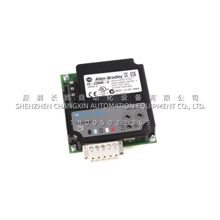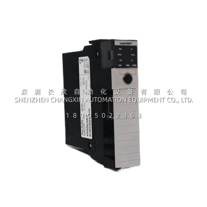
ABB 1SFA892006R1002​ PSS60/105-500L Soft Starter — 60A In-Line / 105A Delta, 208–500V AC, 220–240V AC Ctrl缩略图

ABB 1SFA892006R1002​ PSS60/105-500L Soft Starter — 60A In-Line / 105A Delta, 208–500V AC, 220–240V AC Ctrl

ABB 1SFA892006R1002​ PSS60/105-500L Soft Starter — 60A In-Line / 105A Delta, 208–500V AC, 220–240V AC Ctrl插图


Description

The 1SFA892006R1002​ is an ABB PSS60/105-500L solid-state Soft Starter from ABB’s PSS (Plug-in Solid-State) series, designed to reduce inrush current and mechanical stress during AC induction motor start-up. It supports both in-line (60 A rated) and inside-delta (105 A rated) connection modes for motors up to 30 kW @ 400 V (in-line) or 55 kW @ 400 V (inside-delta). The main circuit operates on 208–500 V AC, with a 220–240 V AC control supply. The 1SFA892006R1002​ features rotary DIP-switch configuration for start/stop ramp time (1–30 s), initial voltage (30–70 %), and current limit (1.5–4 × Ie with external CT), plus built-in run/bypass/fault signal relays — making it a cost-effective, panel-space-saving alternative to star-delta starters in pumps, fans, compressors, and conveyors.

h2 Application Scenarios

In a municipal water pumping station, direct-on-line starting of a 45 kW centrifugal pump causes a violent water-hammer effect in the discharge piping every time the pump kicks in — loosening flange bolts and risking pipe joint failure. By retrofitting the starter panel with the 1SFA892006R1002​ configured for a 5-second voltage-ramp soft start and 3 × Ie current limit, the pump accelerates gradually, eliminating the pressure surge. The built-in bypass relay output can drive an external bypass contactor to remove thyristor heating during continuous run, extending device life. When a supply-phase unbalance occurs, the fault relay on the 1SFA892006R1002​ signals the PLC to inhibit restart — protecting the motor windings. This scenario shows how the 1SFA892006R1002​ directly solves the pain points of destructive inrush current, water hammer, and lack of start-feedback in basic DOL/star-delta setups.

h2 Parameter

Main Parameters Value/Description
Product Model 1SFA892006R1002​ (Type Designation: PSS60/105-500L)
Manufacturer ABB (ABB Motion — Low Voltage Products & Drives)
Product Category Three-Phase AC Motor Soft Starter (Solid-State Reduced Voltage Starter)
Main Circuit Voltage 208 – 500 V AC, 50/60 Hz (Covers 230/400/415/480 V networks)
Rated Current — In-Line 60 A (Max motor ~30 kW @ 400 V AC)
Rated Current — Inside Delta 105 A (Max motor ~55 kW @ 400 V AC)
Control Supply Voltage (Us) 220 – 240 V AC, 50/60 Hz
Start Ramp Time 1 – 30 s adjustable (Voltage ramp-up from initial to full voltage)
Stop (Kick-down) Ramp Time 0 – 30 s adjustable (Soft stop to reduce water hammer)
Initial Starting Voltage 30 – 70 % of mains voltage (rotary switch)
Current Limit Function 1.5 – 4 × Ie (requires external current transformer if used)
Signal Relays 1 × Bypass (NO), 1 × Fault (NO), Run LED indicator
Ambient Temperature -25 °C to +60 °C (no derating to 40 °C)
Mounting Screw-fixed / bolt mount (can be panel or through-bracket); not DIN-rail snap-in
Protection Class IP20 (body), terminals IP10
Certifications CE, cULus, CCC, GOST, IEC 60947-4-2


h2 Technical Principles and Innovative Values

  • Innovation Point 1 — Dual Connection Topology (In-Line & Inside-Delta) in One Compact Unit:​ The 1SFA892006R1002​ uniquely supports inside-delta (Δ) wiring where the starter sees only 1/√3 of the line current — allowing a 60 A-rated device to control a 105 A / 55 kW motor. This flexibility lets specifiers downsize the starter for the same motor power, saving panel space and CAPEX compared to in-line-only designs.
  • Innovation Point 2 — Purely Electromechanical Setup with No Programming Required:​ Unlike digital soft starters needing HMI/software commissioning, the 1SFA892006R1002​ is configured entirely via sealed rotary DIP switches under the front cover — immune to keypad failure, password lock-out, or firmware corruption. This makes it ideal for harsh sites where only electricians (not automation engineers) perform commissioning.
  • Innovation Point 3 — Integrated Bypass & Fault Relays for Seamless External Integration:​ The onboard bypass-relay contact can energize an external 3-pole AC contactor to take over current-carrying duty once the motor reaches full speed, minimizing thyristor heat dissipation. Simultaneously, the NO fault relay provides a dry contact to the plant PLC or alarm annunciator — enabling condition-based rather than time-based maintenance.


h2 Application Cases and Industry Value

Case Study — Food Processing Plant Conveyor Line Upgrade:A snack-food producer experienced frequent belt-joint shear on a 37 kW incline conveyor started DOL. The maintenance team replaced the magnetic starter with a 1SFA892006R1002​ PSS60/105-500L, set for 4 s ramp-up, 2 s soft-stop, and an external bypass contactor triggered by the starter’s bypass relay. Post-retrofit, belt-start jerk was eliminated — no further belt splice failures in 18 months — and the external bypass kept the soft starter cool during 12-hour shifts. The plant reported a 22 % reduction in unplanned conveyor downtime and appreciated the simple DIP-switch setup which required no specialist training. The 1SFA892006R1002​ directly delivered measurable OEE improvement on a modest capital spend.

ABB 1SF536268D1008 PSTX Soft Starter Motherboard — Main Control PCB for PSTX30…PSTX1250 Units缩略图

ABB 1SF536268D1008 PSTX Soft Starter Motherboard — Main Control PCB for PSTX30…PSTX1250 Units

ABB 1SF536268D1008 PSTX Soft Starter Motherboard — Main Control PCB for PSTX30…PSTX1250 Units插图


Description:

The ABB 1SF536268D1008​ is the main control / motherboard PCB (also referred to as the CPU or logic board) used inside ABB’s PSTX series electronic soft starters — covering the PSTX30 through PSTX1250 (certain frame sizes) as well as selected PSR / PSC / PST(B) legacy units that share the same control-platform lineage. It is the intelligence of the soft starter: the board houses the microprocessor that executes the soft-start / soft-stop ramp algorithms (including ABB’s patented TRI LOGIC® for torque-controlled starting), monitors motor current and thyristor heatsink temperature via the power-section sensing links, drives the thyristor gate pulses through an isolated interface, manages the bypass-contactor control, and stores application parameters in non-volatile memory. The 1SF536268D1008​ also provides the connection point for the front keypad/LCD (or remote operator panel) and optionally for a fieldbus piggyback module (Modbus RTU / Profibus / DeviceNet depending on accessory).

Application Scenarios:

A large water-treatment plant operates multiple 315 kW centrifugal pumps on ABB PSTX370 soft starters. During a hot summer afternoon, one starter faulted to “Control Board Failure / EEPROM Error” and would not reset via the front panel or by cycling power. The pump was critical to maintaining wet-well level. Maintenance verified 110 V AC control voltage was present and reseated the ribbon to the keypad — the fault persisted, indicating a failed ABB 1SF536268D1008​ motherboard. A pre-verified spare was installed (after isolating main power and discharging the DC bus), the original DIP / jumper settings were replicated, and the starter booted normally — loading its parameter set from the onboard NVRAM. The pump was back online within 20 minutes, avoiding a bypass around the soft starter that would have subjected the motor to a damaging across-the-line start and potentially tripped the upstream MCCB. The 1SF536268D1008​ directly solved the pain point of a “brain-dead” soft starter — when this board fails the thyristors cannot fire and the motor cannot start, making it the single highest-priority spare for any PSTX-equipped facility.

Parameter:

Main Parameters Value/Description
Product Model 1SF536268D1008​ (PSTX Series Main Control / Motherboard PCB)
Manufacturer ABB (Drives / Motion — Low Voltage Products & Systems)
Product Category Soft Starter Control Board / CPU Motherboard (PSTX Family)
Compatible Starters ABB PSTX30 … PSTX570 (some references extend to PSTX1250 — verify BOM / frame size before order)
Microprocessor 16-bit / 32-bit MCU (version-dependent) executing ramp, current-limit & TRI LOGIC® algorithms
Memory NVRAM / EEPROM for parameter storage; retentive across power cycles
Inputs (Control Side) Run / Stop / Reset DI (24 V DC or 110/230 V AC per version); optional remote DI expansion via add-on
Outputs (Control Side) Bypass contactor drive (relay or SSR), Fault Relay (NO/NC), Ready / Running status
Thyristor Interface Isolated gate-drive & feedback via multi-pin header to power-section firing board
Sensing Inputs Motor current (CT secondary from power section), heatsink temperature (NTC/PTC from thyristor module)
Keypad / Display Ribbon cable to PSTX front panel (2-line alpha-numeric + LEDs) or remote mount kit
Option Slot Supports fieldbus piggyback (Modbus RTU / Profibus DP / DeviceNet — sold separately)
Supply Voltage Derived from soft starter control-voltage input (typically 100–240 V AC or 24 V DC — per starter P/N)
Coating / Protection Conformal coated PCB; IP00 (must be installed inside starter enclosure)
Operating Temp. -10 °C to +50 °C (inside starter cabinet; derate above 40 °C per manual)
Dimensions (approx.) 150 × 110 × 30 mm (form factor varies by PSTX frame size — confirm against removed unit)


Technical Principles and Innovative Values:

The ABB 1SF536268D1008​ is purpose-built for reliable, repeatable motor starting — not a generic motor-controller card.

  • Innovation Point 1 — TRI LOGIC® Torque-Controlled Starting & Kick-Start Feature:​ The onboard firmware implements ABB’s TRI LOGIC® algorithm which modulates starting torque in proportion to load requirement rather than blindly ramping voltage. This reduces mechanical stress on couplings/belts and minimizes starting current spikes — a key advantage over basic voltage-ramp soft starters and a frequent reason plants standardize on PSTX units.
  • Innovation Point 2 — Dual-Level Parameter Protection & Auto-Restore:​ Application parameters (ramp time, initial/final voltage, current limit, bypass delay) are stored in write-protected NVRAM. If a board is replaced, the new 1SF536268D1008​ can be pre-loaded from a backup file via ABB’s starter-configuration software, or will adopt the previous unit’s settings if the old EEPROM is transplanted (version-dependent). This minimizes recommissioning time.
  • Innovation Point 3 — Integrated Bypass Logic with Reduced Heat & Energy:​ The control board automatically closes the external bypass contactor once the ramp is complete and motor current has settled below the preset bypass-current threshold. This removes thyristor conduction losses, extends SCR life, and improves overall system efficiency — all sequenced by the 1SF536268D1008​ without external timer relays.
ABB 1SDA064796R1: Tmax XT Series MCCB Auxiliary Switch / Control Module (1SDA06 Accessory)缩略图

ABB 1SDA064796R1: Tmax XT Series MCCB Auxiliary Switch / Control Module (1SDA06 Accessory)

ABB 1SDA064796R1: Tmax XT Series MCCB Auxiliary Switch / Control Module (1SDA06 Accessory)插图


Description

The 1SDA064796R1​ is a switch-type accessory module (commonly an auxiliary contact block, control switch, or motor-operator component depending on the specific breaker configuration) manufactured by ABB under the SACE Tmax 1SDA06 accessory series. It is designed to snap directly onto the left- or right-hand side of ABB Tmax XT series molded-case circuit breakers (MCCB)—XT1 through XT4 frames—providing breaker position feedback (ON/OFF/TRIP) to a PLC/DCS or enabling remote electrical operation / control interlocking without modifying the breaker’s primary protection function.

Application Scenarios

Imagine a water-treatment plant where the main 400 V distribution board uses ABB Tmax XT2 MCCBs to protect large pump feeders. During a routine panel audit, the maintenance team discovers that one pump’s SCADA shows no “Breaker Closed” status—the original auxiliary contact block has failed mechanically after 15 years of thermal cycling. Rather than replace the entire MCCB (which would mean de-energizing the busbar, unbolting heavy Cu bus joints, and re-terminating), the electrician simply isolates the individual breaker, snaps out the failed accessory, and clicks a new 1SDA064796R1​ into the same side slot. The contact block’s SPDT contacts immediately feed correct ON/OFF status to the PLC, and the pump’s auto-start logic is restored—all in under 10 minutes with zero disturbance to adjacent circuits. The 1SDA064796R1​ solves the common pain point of aged MCCB accessories in live panels, letting plants refresh only the worn control element while preserving the certified protection device and its terminations.

Parameter

Main Parameters Value/Description
Product Model 1SDA064796R1​ (SACE Tmax 1SDA06 Accessory Series)
Manufacturer ABB
Product Category MCCB Accessory — Auxiliary Switch Block / Control Module (clip-on side mount)
Compatible Breakers ABB SACE Tmax XT1, XT2, XT3, XT4 (also selected Tmax T series frames — verify per breaker type)
Function Auxiliary contact (typically 1NO+1NC or 2NO+2NC SPDT), or specified shunt/UV release / motor operator variant per 1SDA064796R1 subtype
Contact Rating 6 A @ 250 V AC / 16 A @ 24 V DC (typical auxiliary contact rating — verify against your exact accessory type)
Control Voltage (if motorized/shunt) Common 24 V DC / 110–240 V AC (must match ordered variant; check breaker’s accessory code)
Mounting Method Clip-on / slide-in to dedicated left or right accessory slot on Tmax XT breaker — no tools beyond small flat-blade for terminal screws
Electrical Life ≥ 10,000 operations @ rated load (aux contact); ≥ 6,000 ops (motor operator variants)
Mechanical Life ≥ 100,000 operations (aux contact block)
Operating Temp. -25 °C to +70 °C
Protection Class IP20 (when installed inside breaker — overall assembly IP30–IP40 dependent on MCCB enclosure)
Standards / Certifications IEC 60947-1 / IEC 60947-2, CE, CCC, UL, CSA
Dimensions (Approx.) 45 × 70 × 25 mm (compact side-mount module)
Weight (Approx.) 0.06–0.10 kg


Technical Principles and Innovative Values

  • Innovation Point 1 — Tool-Free Clip-On Side Mounting:​ The 1SDA064796R1​ is engineered with a molded dovetail that snaps positively into the pre-machined accessory slot of any compatible Tmax XT breaker. No disassembly of the MCCB, no special tools, and no busbar disturbance—this modular “add-as-needed” design lets panels be commissioned with minimal accessories initially and upgraded later without downtime on adjacent circuits.
  • Innovation Point 2 — Positive Mechanical Linkage to Breaker Operating Mechanism:​ Unlike add-on external microswitches, the 1SDA064796R1​ couples directly to the breaker’s operating shaft / trip bar. It distinguishes true TRIP (mechanically latched trip position) from manual OFF—a critical distinction for DCS alarm logic that differentiates a protective trip from an operator-initiated open command.
  • Innovation Point 3 — Front-Accessible Screw Terminals with Clear Marking:​ All contact terminals are brought to the front face with embossed A1/A2/11-12-14 markings, allowing panel builders and maintenance staff to land control wires cleanly even in dense panels. The block is keyed to prevent incorrect insertion, and its silver-cadmium oxide (AgCdO) or silver-nickel contacts deliver low contact resistance over decades of service.
ABB 1SDA038324R1: 220–240 V AC / 220–250 V DC Motor Operator Kit for Emax / XT Air Circuit Breakers缩略图

ABB 1SDA038324R1: 220–240 V AC / 220–250 V DC Motor Operator Kit for Emax / XT Air Circuit Breakers

ABB 1SDA038324R1: 220–240 V AC / 220–250 V DC Motor Operator Kit for Emax / XT Air Circuit Breakers插图


Description

The ABB 1SDA038324R1​ is a Motor Operator (Motorized Closing / Spring-Charging Unit) accessory designed for ABB SACE series low-voltage power circuit breakers — including Emax (E1/E2/E3/E4/E6), Tmax XT (larger frame sizes), and Isomax S series where motor-operation is specified. It electrically charges the breaker’s spring-closing mechanism and/or provides motorized OPEN/CLOSE capability when interfaced with a shunt trip, undervoltage release, and closing coil via the breaker’s control circuit — enabling remote breaker operation from MCC, SCADA, or DCS.


Application Scenarios

A data-center 10 kV / 400 V main distribution board used an ABB Emax E3 air circuit breaker (ACB) as the incomer. Manual operation was acceptable during commissioning, but the facility’s NOC (Network Operations Center) required remote open/close capability for load-shedding and generator-transition sequences. The electrical contractor installed the ABB 1SDA038324R1 Motor Operator​ inside the ACB’s right-side accessory compartment, wired to the building’s 230 V AC UPS-backed auxiliary supply and controlled via the BMS through a PLC dry-contact. During monthly generator-test drills, the NOC remotely opens the utility incomer (via shunt trip) and closes the gen-set ACB — then reverses the sequence — all without sending a technician to the LV switchroom. The facility engineer commented: “Adding the 1SDA038324R1​ motor operator turned our manual main breaker into a fully remotely operable asset. The kit snapped into the factory-prepared mounting points, and the only extra wiring was the 230 V supply and control leads. It’s been 100 % reliable through three years of weekly test cycles.”


Parameter

Main Parameters Value/Description
Product Model 1SDA038324R1​ (also referenced as 1SDA038324R)
Manufacturer ABB (SACE — Low Voltage Breaker Accessories)
Product Category Motor Operator / Motorized Spring-Charging & Closing Unit (ACB Accessory)
Compatible Breakers ABB SACE Emax E1 / E2 / E3 / E4 / E6; Tmax XT > 630 A frames; Isomax S2–S6 (where MO listed)
Motor Supply Voltage Typically 220–240 V AC 50/60 Hz or 220–250 V DC (verify coil code suffix per breaker rating)
Rated Operating Time Spring charge time ≤ 0.3–0.6 s (Emax E1/E2); ≤ 1.0 s (E3/E4/E6) after release
Duty Cycle Intermittent (motor runs only during spring charging; not continuously energized)
Closing Method Charges springs → mechanical closing via stored-energy release (not direct motor-close)
Mounting Location Dedicated motor-operator compartment on left / right side of breaker (frame-specific)
Terminals Screw / spring-cage terminals for motor supply & auxiliary micro-switch contacts
Ambient Temp. -5 °C to +55 °C (some refs -25 °C to +70 °C for stored / transport)
Standards IEC 60947-2, IEC 62271-100 (influence), UL 489 / UL 1066 listed (with host breaker)
Included Items Motor unit, mounting bracket/hardware, auxiliary limit switch (spring-charged / motor-running), installation leaflet
Notes Must be ordered matched to breaker frame size & coil voltage; not a universal fit across all SACE models


Technical Principles and Innovative Values

The ABB 1SDA038324R1​ is engineered as a reliable, stored-energy motorization solution:

  • Innovation Point 1 — Stored-Energy Spring-Charging Principle:​ The motor does NOT directly close the breaker contacts. It drives a reduction gear to tension the breaker’s closing springs; a micro-switch cuts power when the spring is fully charged. The actual closing is executed by the breaker’s mechanical release — ensuring consistent closing speed and contact pressure regardless of supply voltage sag, and preventing “teasing” (slow close) that could weld contacts.
  • Innovation Point 2 — Factory-Engineered Mount & Interlock Compatibility:​ The 1SDA038324R1​ is dimensioned for the specific breaker frame’s accessory cavity with pre-drilled locating tabs and captive screws. It mechanically interlocks with the breaker’s racking mechanism — the motor cannot be energized unless the breaker is in the CONNECTED or TEST position (per draw-out configuration), preventing unsafe operation.
  • Innovation Point 3 — Integrated Auxiliary Micro-Switches:​ The unit includes a “Springs Charged” (52a) and “Motor Running” contact as standard. These can be wired to the control system to annunciate readiness and block a close command if the spring is not charged — a critical interlock in pump-storage, generator-parallel, and auto-changeover schemes.
  • Innovation Point 4 — Robust DC / AC Universal Motor Design (selected versions):​ Certain coil variants accept both AC and DC supply, allowing the same motor operator to be used in DC-battery-backed UPS panels and standard AC MCCs — simplifying spare-parts inventory across mixed-voltage sites.
ABB 1SBP260102R1001 XC08L1 Digital I/O Extension Module – 8 Configurable 24 V DC Channels for AC500缩略图

ABB 1SBP260102R1001 XC08L1 Digital I/O Extension Module – 8 Configurable 24 V DC Channels for AC500

ABB 1SBP260102R1001 XC08L1 Digital I/O Extension Module – 8 Configurable 24 V DC Channels for AC500插图


Description:

The ABB 1SBP260102R1001, also designated as XC08L1, is a configurable Digital I/O Extension Module within ABB’s AC500 / XC-series automation platform. It provides 8 independent digital channels—each individually software-selectable as a 24 V DC digital input or a 24 V DC transistor output (max. 0.5 A)—and connects to the AC500 CPU or a local I/O head module via the short expansion bus ribbon / plug. Its mixed-signal flexibility makes it ideal for compact machines or retrofit panels where point counts are modest and mixing inputs and outputs on one module reduces spare-parts variety.


Application Scenarios:

Picture a packaging machine OEM that originally designed a control panel with 6 pushbutton/EO-Stop inputs and 4 pilot-lamp / small-solenoid outputs. Rather than stocking both an 8-DI and an 8-DO card—half of whose points would sit unused—the integrator specifies the ABB 1SBP260102R1001 (XC08L1). During commissioning in Automation Builder, channels 0–2 are configured as sinking digital inputs (reading NPN prox sensors and E-Stop contacts), while channels 3–5 are set as sourcing 24 V DC outputs driving 0.3 A indicator beacons and a pneumatic dump valve. The sixth channel is left unused but available for future options. When a machine is later modified in the field to add a guard-door interlock, the maintenance technician simply re-assigns an unused channel to “Input” in the software and wires the contact—no hardware swap required. The per-channel front LEDs let line operators instantly see which sensor or output is active during fault-finding, cutting diagnostic time from minutes to seconds on a busy production floor.

Parameter:

Main Parameters Value/Description
Product Model 1SBP260102R1001​ (Type: XC08L1)
Manufacturer ABB Automation (Switzerland / Sweden)
Product Category Digital I/O Extension Module (Configurable per Channel)
System Compatibility ABB AC500 Series PLC (PM5xx CPUs) / XC Local I/O Bus
Number of Channels 8 (each individually configurable as DI or Transistor DO)
Input Type / Voltage 24 V DC (sink/source capable), typical threshold ≈ 15 V
Output Type / Current 24 V DC Solid-State (High-Side), max. 0.5 A per channel
Process Supply Voltage 24 V DC (terminals UP/ZP), range 20.4 – 28.8 V DC
Response Time < 1 ms (typical for both DI filtering and DO switching)
Isolation Galvanic isolation between I/O bus side and field terminals
Status Indication 1 × PWR LED, 1 × BUS/RUN LED, 8 × channel LEDs (green = active)
Connection Type Spring-cage or screw terminal block (per sub-version), expansion bus plug
Mounting Method 35 mm DIN rail (EN 60715)
Operating Temperature –25 °C to +60 °C
Protection Class IP20 (for installation inside enclosed control cabinet)
Dimensions (approx.) 102 × 76 × 60 mm (W × H × D), Weight ≈ 0.18–0.22 kg
Certifications CE, cULus, RoHS-compliant per ABB system certification


Technical Principles and Innovative Values:

  • Innovation Point 1: Per-Channel Software-Selectable I/O Direction.​ Unlike fixed DI or DO modules, the ABB 1SBP260102R1001​ lets engineers assign each of the 8 channels independently as input or output in the Automation Builder hardware configuration. This “mix-and-match” capability halves the number of spare module types a plant must stock and adapts to last-minute panel-design changes without hardware rework.
  • Innovation Point 2: Individual Channel LEDs for Rapid Troubleshooting.​ Each I/O point has its own front-panel LED. When a guard-door input closes or an output energizes a solenoid, the corresponding LED lights—enabling first-pass visual verification on the shop floor without a programming laptop or multimeter, a crucial time-saver during unplanned stops.
  • Innovation Point 3: Short-Bus Local Expansion with Integrated Diagnostics.​ The XC08L1​ connects via the AC500 local I/O expansion connector (flat-cable or plug-in header), drawing both process power and communication from the bus. Built-in open-load detection on outputs and input-line monitoring report anomalies to the CPU, turning silent field-wiring faults into visible alarms rather than mysterious logic mismatches.
ABB 1N1346 12 Amp 600 Volt Standard Recovery Diode — Direct Fit for Westinghouse / GE Equivalent Replacements缩略图

ABB 1N1346 12 Amp 600 Volt Standard Recovery Diode — Direct Fit for Westinghouse / GE Equivalent Replacements

ABB 1N1346 12 Amp 600 Volt Standard Recovery Diode — Direct Fit for Westinghouse / GE Equivalent Replacements插图

Description:

The 1N1346​ is an ABB / former Westinghouse / International Rectifier heritage standard-recovery silicon rectifier diode housed in a threaded stud-mount package (typically DO-4 / DO-5 / DO-203AB style). Rated at 12 A average forward current and 600 V peak reverse voltage, it is designed for general-purpose AC-to-DC rectification, free-wheeling, DC link blocking, and snubber diode duties in industrial drive power sections, welding machines, battery chargers, and vintage control-circuit power supplies where fast-recovery (FRD) characteristics are not required.h2 Application Scenarios:A steel service center still operating a 1980s vintage DC drive-controlled bar shear was experiencing erratic DC bus regulation and occasional fuse blowing on the three-phase bridge rectifier feeding the armature circuit. Visual inspection revealed one of the six original stud-mounted rectifiers had cracked and the anode lead had oxidized. The OEM part cross-referenced to the 1N1346. The maintenance electrician removed the faulty diode—undoing the 10-32 stud nut and two ring-terminal screws—cleaned the mating surfaces with fine emery cloth, applied a thin layer of thermal compound, torqued the new 1N1346​ to spec, and reconnected the leads. The drive powered up cleanly; DC bus ripple returned to within original design limits and the intermittent overcurrent trips ceased. The plant’s drive specialist commented that having the correct 1N1346​ standard-recovery diode on the shelf “saved a day of hunting for obsolete parts and kept the shear in production during peak shipping season.” This is the classic role of the 1N1346: an unsung but essential component whose correct specification—standard (not fast) recovery, appropriate VRRM, and stud-mount ruggedness—is critical when replacing originals in legacy power electronics.h2


Parameter:

Main Parameters Value/Description
Product Model 1N1346​ (also cross-listed as 1N1346A, JAN1N1346 depending on screening)
Manufacturer ABB (heritage Westinghouse / IR / SEMIKRON cross-reference)
Product Category Standard Recovery Silicon Rectifier Diode (Stud Mount)
Average Forward Current (IF(AV)) 12 A @ TC= 55 °C (case temp), derated per heatsink
Peak Reverse Repetitive Voltage (VRRM) 600 V
Forward Voltage Drop (VF) ≤ 1.1 – 1.3 V @ 12 A (typical for silicon standard recovery)
Reverse Leakage Current (IR) ≤ 1 mA @ VRRM, 25 °C
Non-Repetitive Surge (IFSM) 250 – 300 A (1 cycle, 60 Hz sine)
Recovery Time (trr) Standard recovery (~ 3 – 5 µs typical; NOT a fast-recovery diode)
Package Style DO-5 / DO-203AB — threaded stud (¼–28 UNF typical) + two solder / pressure tabs or axial leads per variant
Cathode / Anode Identification Stud = Cathode (on most 1N1346; stud = Anode on “R” variants — verify marking)
Operating Junction Temp. -65 °C to +175 °C
Mounting Torque 8 – 12 in-lb (0.9 – 1.4 N·m) on stud nut; use thermal grease for heatsink mating
Qualification / Screening Commercial / JAN / JANTX available per vintage batch
Key Note Match polarity (stud cathode vs. stud anode) to the removed unit before installation


h2 Technical Principles and Innovative Values:

  • Innovation Point 1 — Robust Diffusion-Junction Silicon Design for High Surge Withstand.​ The 1N1346​ employs a diffused p-n junction optimized for standard-recovery rectification rather than fast switching, giving it excellent tolerance to high non-repetitive surge currents (up to 250 A+ for a half-cycle). This makes it ideal for line-frequency bridge rectifiers where momentary inrush from capacitive DC-link charging or transformer magnetizing current would destroy a smaller signal diode.
  • Innovation Point 2 — Threaded Stud Mounting for Low Thermal & Electrical Resistance.​ Unlike press-fit or surface-mount diodes, the 1N1346​ mounts via a ¼–28 UNF threaded stud directly into a tapped hole or through-bolted with nut on a machined heatsink. Properly torqued with thermal compound, this provides a low-ohmic path for both heat (to the sink) and return current (through the stud), ensuring the diode operates within its 12 A rating even in warm cabinet environments.
  • Innovation Point 3 — MIL-Spec Heritage & Cross-Industry Interchangeability.​ Originally qualified to MIL-SPEC (JAN / JANTX classes), the 1N1346​ remains backward-compatible with countless legacy drive, welder, and plating-rectifier designs. It directly replaces 1N1190, 1N1202, and many OEM-specific stud diodes of equivalent VRRM/ IF, making it a versatile single-part inventory item for plants maintaining mixed-vintage equipment.

h2 Application Cases and Industry Value:Case — Plating Shop 3-Phase Bridge Rectifier Overhaul:​ An electroplating line used a 500 A 12 V DC rectifier built from six stud-mounted diodes in a full-wave bridge. Two diodes failed after 15 years of continuous duty. The original OEM part was discontinued; cross-reference pointed to the ABB 1N1346​ (12 A rating sufficient for the control / pilot supply bridge of the regulator, not the main 500 A stack—those used larger 1N3208-class units). The control bridge was rebuilt with six new 1N1346​ diodes, restoring the automatic voltage-regulation reference circuit. The plating shop supervisor noted that “the reference was rock-steady again—no more wandering bath voltage,” and the 12-per-diode spend prevented a 4,000 new rectifier controller purchase.

ABB 1SBP260102R1001 XC08L1: 24 V DC 0.5 A Output, <1 ms Response, DIN Rail Mount I/O Expander缩略图

ABB 1SBP260102R1001 XC08L1: 24 V DC 0.5 A Output, <1 ms Response, DIN Rail Mount I/O Expander

ABB 1SBP260102R1001 XC08L1: 24 V DC 0.5 A Output, <1 ms Response, DIN Rail Mount I/O Expander插图


Description:

The ABB 1SBP260102R1001, marketed as the XC08L1, is a configurable Digital I/O Extension Unit within ABB’s XC / AC500-compatible I/O family. It provides eight independently configurable 24 V DC digital channels—each individually software-assignable as a sinking/sourcing input or a transistor output (0.5 A per channel)—and connects to the controller via the local I/O extension bus or a remote coupler. This flexibility allows one module type to serve as either DI, DO, or a mixed I/O block, reducing spare-parts diversity while extending the signal-interface capacity of ABB PLC and automation systems in machine, process, and building-control applications.


Application Scenarios:

Consider a packaging-line retrofit where the original ABB AC500 CPU with 16 DI + 16 DO is fully allocated, but the new design adds two photoelectric sensors on the infeed and a pneumatic ejector solenoid on the reject station—three extra points total. Rather than replacing the entire I/O rack with a larger (and costlier) module set, the integrator clips the 1SBP260102R1001​ (XC08L1) onto the existing 35 mm DIN rail, daisy-chains the short CS31/expansion flat cable to the CPU’s last I/O head, and configures Ch1–Ch2 as 24 V DC inputs (sensors) and Ch3 as a digital output (solenoid). The remaining five channels are left unused or reserved for future expansion. The 1SBP260102R1001​ powers up, auto-enumerates on the bus, and the per-channel yellow LEDs confirm signal presence during commissioning—no separate input card, no separate output card, no rewiring of the existing points. The key pain point solved: adding small, mixed-signal I/O increments to a running system with minimal panel space, zero disruption to existing wiring, and reduced spare-inventory SKUs.


Parameter:

Main Parameters Value/Description
Product Model 1SBP260102R1001​ (XC08L1)
Manufacturer ABB (Switzerland / Sweden)
Product Category Digital I/O Extension Unit / Configurable 8-Channel DI/DO Module
System Compatibility ABB AC500 / AC500-eCo PLCs, ABB Advant Controller 31 (select), XC-series I/O stations
Number of Channels 8 channels, each independently configurable as DI or Transistor DO (24 V DC)
Input Voltage (DI Mode) 24 V DC (operating range 20.4–28.8 V DC); typical threshold ON ≈ 15 V DC
Output Type (DO Mode) Solid-state transistor (sinking or sourcing per wiring); 0.5 A max per channel, total module limit applies
Response Time < 1 ms (typical input filter / output update)
Isolation Galvanic isolation ≥ 1.5 kV AC between field-side I/O bus and system backplane/logic
Indicators Power LED (green), Bus/Run LED (green), per-channel Status LED (yellow)
Supply Voltage 24 V DC (external auxiliary or via I/O bus depending on carrier)
Mounting 35 mm DIN rail (EN 60715 / TS35) – snap-on with retaining screw
Operating Temp. -25 °C to +60 °C (storage: -40 °C to +85 °C); 5–95 % RH non-condensing
Protection Class IP20 (for installation inside enclosed control cabinet)
Certifications CE, cULus, RoHS, IEC 61131-2 compliant


Technical Principles and Innovative Values:

The 1SBP260102R1001​ (XC08L1) is a user-flexible I/O slice that trades rigid input-only / output-only partitioning for per-point configurability under software control.

  • Innovation Point 1: Per-Channel Software-Selectable Direction Eliminates Fixed I/O Type Spares.​ The 1SBP260102R1001​ allows each of its eight channels to be set as DI or DO in the Automation Builder / Control Builder project tree. A plant can standardize on a single spare part number to cover both 8DI and 8DO failure scenarios—just download the appropriate configuration. This halves the minimum recommended spare SKUs for small-to-midsize I/O fleets and simplifies obsolescence planning.
  • Innovation Point 2: Integrated Diagnostics & Visual Channel Verification.​ Every channel on the 1SBP260102R1001​ has its own yellow LED, and the module reports power-on self-test, bus-communication loss, and output short-circuit/overload events to the CPU’s diagnostic buffer. During commissioning or fault-finding, technicians can confirm sensor activation or output command state through the cabinet door window without a multimeter or laptop—accelerating MTTR.
  • Innovation Point 3: Compact Footprint with Deterministic Local-Bus Timing.​ Occupying only one slim slot on the DIN rail (≈12–20 mm width depending on carrier), the 1SBP260102R1001​ connects via the proven ABB local I/O bus or CS31 extension link. Scan/update timing is deterministic and synchronized with the PLC task cycle (< 1 ms effective response), making it suitable for real-time machine-control loops—not just slow-status monitoring.
ABB 1SBP260102R1001 XC08L1 Digital I/O Extension Unit – 8 DI + 8 DO Expansion for AC31 / Freelance缩略图

ABB 1SBP260102R1001 XC08L1 Digital I/O Extension Unit – 8 DI + 8 DO Expansion for AC31 / Freelance

ABB 1SBP260102R1001 XC08L1 Digital I/O Extension Unit – 8 DI + 8 DO Expansion for AC31 / Freelance插图

Description

The ABB 1SBP260102R1001, commercially identified as the XC08L1, is a compact local Digital Input / Digital Output (DI/DO) extension unit for ABB AC31 series programmable logic controllers and early Freelance installations. It adds eight 24 V DC discrete inputs and eight discrete outputs (transistor or relay version depending on sub-type) to a CPU or communication/interfacing module such as the CE32 or SA811, connecting via a short proprietary ribbon or flat cable to the controller’s local expansion bus. The XC08L1​ is housed in a DIN-rail mountable enclosure and is ideal for small- to medium-machine control, building automation, and auxiliary process skids where additional local I/O is needed close to the controller.h2 Application ScenariosConsider a regional bottling plant still running a reliable ABB AC31-50 CPU to sequence fill-heads, cappers, and conveyor star-wheels. The original panel had exactly enough I/O for the base machine, but a recent packaging-line upgrade added two new pneumatic reject gates and a “Case Present” photo-eye—requiring four extra DI points and two extra DO points. Rather than installing a full remote I/O rack with power supply, communication module, and new cabling, the panel builder simply snaps a ABB 1SBP260102R1001 (XC08L1)​ onto the DIN rail adjacent to the CPU, connects the included expansion cable to the controller’s local bus port, and lands the new field wires on the XC08L1’s screw terminals. The CPU auto-detects the extension; the programmer assigns the new %IX / %QX addresses in PG2000 / Automation Builder and downloads—no additional communication configuration needed. This scenario shows the XC08L1​ solving a classic pain point: adding modest local I/O quickly, cheaply, and with zero network overhead, extending the useful life of proven AC31 hardware.h2


Parameter

Main Parameters Value/Description
Product Model 1SBP260102R1001​ (XC08L1)
ABB Type Designation XC08L1
Manufacturer ABB (Industrial IT / AC31 Series)
Product Category Local Digital I/O Extension Unit (Plug-On / Cable Connected)
Digital Inputs (DI) 8 × 24 V DC (12–30 V DC range), sink/source selectable per common group (typical)
Input Current (per ch.) ≈ 4–7 mA @ 24 V DC
Digital Outputs (DO) 8 × (Transistor NPN/PNP or Relay NO — verify sub-variant by label: XC08L1-Relay vs XC08L1-Transistor)
Output Rating (Transistor) 0.5 A @ 24 V DC (per point, short-circuit protected)
Output Rating (Relay) 2 A @ 250 V AC / 30 V DC (NO contact, resistive)
Isolation I/O circuits isolated from internal bus; outputs group-wise isolated (relay version) or common (transistor version)
Connection Method Screw terminals (field I/O) + 10-/14-way flat-cable to controller local-bus port
Indicators Power LED + per-channel status LEDs (Input ON / Output ON)
Supply Voltage 24 V DC (±20 %) — typically daisy-chained from CPU / PS power supply
Operating Temperature 0 °C to +55 °C (IEC 61131-2, Class I)
Mounting 35 mm DIN Rail (EN 50022)
Dimensions (H×W×D) ≈ 90 × 72 × 60 mm (typical for AC31 compact XC units)
Weight ≈ 0.18 kg


*Note: Confirm whether your XC08L1 is the transistor (solid-state) or relay-output version by checking the removed unit’s label before ordering — mixing types can affect load compatibility.h2 Technical Principles and Innovative ValuesThe XC08L1​ is designed as a low-overhead local expansion for the AC31 ecosystem.

  • Innovation Point 1 – Bus-Powered Local Expansion with Auto-Enumeration: The 1SBP260102R1001​ connects to the AC31 CPU or CE32 extension interface via a short parallel/expansion cable. The controller automatically detects the module at boot and assigns consecutive I/O addresses—no GSD file import, no baud-rate setting, no terminator resistor. This makes adding I/O genuinely plug-and-play within the local rack area.
  • Innovation Point 2 – Mixed DI/DO in Minimal Footprint: Packaging 8 DI + 8 DO in a 72 mm wide housing, the XC08L1​ conserves DIN-rail space compared to installing separate DI and DO slices. Each DI channel has LED indication and a typical 3 ms filter to reject contact bounce, while DO channels feature short-circuit / overload protection (transistor version) or contact-rated isolation (relay version), reducing the need for auxiliary interposing relays on small loads.
  • Innovation Point 3 – Seamless Integration with Legacy AC31 Engineering Tools: The XC08L1​ is natively supported in ABB PG2000, Control Builder F (Freelance older builds), and Automation Builder (legacy mode). I/O symbols can be drag-dropped into the variable table; forcing/overriding outputs for commissioning is done through the standard online debug window—no special driver or add-on package required.
ABB 1SBP260056R1001 ICMK-CS31 Advant Controller 31 Remote Unit – CS31 Bus Coupler & I/O Head缩略图

ABB 1SBP260056R1001 ICMK-CS31 Advant Controller 31 Remote Unit – CS31 Bus Coupler & I/O Head

ABB 1SBP260056R1001 ICMK-CS31 Advant Controller 31 Remote Unit – CS31 Bus Coupler & I/O Head插图


Description:

The ABB 1SBP260056R1001, also identified as the ICMK-CS31 Remote Unit, is a bus-coupling / remote I/O head module for ABB’s Advant Controller 31 (AC31) series and compatible CS31 network architectures. It serves as the intelligent interface between a CS31 master (AC31 CPU) and locally mounted S500-series I/O modules (digital input/output, analog input/output, etc.), enabling distributed signal acquisition and control up to 500 m from the main control cabinet without running individual field cables back to the PLC.

Application Scenarios:

A bottling plant’s main filling line was being extended by 40 meters to add a new accumulation conveyor and a reject station. Running dozens of individual 24 V DC sensor and solenoid cables back to the central AC31 PLC panel would have meant expensive conduit work, long lead times, and increased EMI risk. Instead, the integrator installed an ABB 1SBP260056R1001 (ICMK-CS31)​ remote unit in a small local junction box at the line extension, clipped two S500 I/O slices (one 16DI + one 16DO) onto its right-hand expansion bus, set the rotary address switch to Node 5, and ran a single shielded twisted-pair CS31 cable (~60 m) back to the AC31 master rack. Within one afternoon the new conveyor sensors and reject pusher solenoids were online — configured directly from the existing PLC program with no new CPU or rack required. The ICMK-CS31​ turned what would have been a cabling nightmare into a clean, cost-effective distributed I/O solution, eliminating hundreds of meters of copper and significantly reducing commissioning time.

Parameter:

Main Parameters Value/Description
Product Model 1SBP260056R1001​ (ICMK-CS31)
Manufacturer ABB
Product Category Advant Controller 31 – Remote Unit / CS31 Bus Coupler (I/O Head Module)
Compatible System ABB Advant Controller 31 (AC31-40 / AC31-50), CS31 Network
Supply Voltage 24 V DC (19.2 – 30 V DC allowable range)
Power Consumption < 2.5 W (excluding connected I/O modules)
Communication Bus CS31 (RS-485 physical layer, ABB proprietary master-slave protocol)
Bus Data Rate 187.5 kbit/s
Max. Bus Length 500 m (unrepeated), extendable with repeaters
Max. Slaves per Master 31 CS31 nodes
Local I/O Expansion Up to 6 or 7 S500-series I/O modules (digital / analog / special) on right-side bus
Node Addressing Rotary DIP switch (0 – 31) on front panel
Status Indication PWR (power), RUN (active on CS31), ERR (fault/bus error) LEDs
Operating Temperature -25 °C to +60 °C
Storage Temperature -40 °C to +85 °C
Mounting Method 35 mm DIN rail (EN 60715), screw-terminal wiring
Protection Class IP20 (for installation inside enclosed cabinet / local box)
Dimensions (approx.) 90 × 140 × 70 mm (W × H × D, including terminals)
Weight (approx.) 0.30 – 0.35 kg


Technical Principles and Innovative Values:

  • Innovation Point 1 — Transparent I/O Mapping over CS31.​ The ABB 1SBP260056R1001​ automatically exchanges process-image data with the AC31 master every scan cycle. All locally connected S500 I/O points appear in the master PLC’s I/O image table as if they were in the main rack — no messaging instructions or custom protocol coding required, simplifying engineering and reducing scan-time overhead.
  • Innovation Point 2 — Modular S500 I/O Expansion Without a CPU.​ The ICMK-CS31 itself contains no user program; it acts purely as a bus-activated I/O aggregator. Up to 6–7 S500 modules can be snapped onto its right-side expansion bus, mixing DI, DO, AI, AO, and temperature-input slices as needed — making it exceptionally flexible for varied field signal mixes.
  • Innovation Point 3 — Front-Panel Diagnostics & Address Security.​ A three-LED status cluster (PWR / RUN / ERR) gives immediate go/no-go indication of power, bus communication, and fault conditions. The recessed rotary address switch prevents accidental mis-addressing during maintenance, and a watchdog timer automatically forces outputs to safe state if CS31 communication is lost — a critical safeguard in distributed machine control.


Application Cases and Industry Value:

Case – Automotive Parts Washer Distributed I/O Upgrade:​ A tier-1 automotive supplier operated a multi-stage parts washer with pump skids located 80 m from the main AC31 control panel. Originally wired with parallel multicore cables, repeated flexing and wash-down exposure caused intermittent opens that were difficult to trace. During a planned downtime window the plant installed two ABB 1SBP260056R1001 (ICMK-CS31)​ remote units — one at each pump skid — each with local S500 DI (float-switch & pressure-switch monitoring) and DO (pump start/stop, solenoid valves) modules. A single CS31 cable linked both remote stations back to the master rack. Post-conversion, all pump status signals updated in <20 ms, wiring fault calls dropped to zero, and the plant documented a 70 % reduction in troubleshooting time for washer I/O issues. The ICMK-CS31​ delivered a robust, noise-immune distributed I/O architecture that extended the life and reliability of the legacy AC31-based control system.

ABB 07CR41 1SBP260020R1001 AC31 90-Series PLC Basic CPU Unit with 8 DI / 6 DO Relay缩略图

ABB 07CR41 1SBP260020R1001 AC31 90-Series PLC Basic CPU Unit with 8 DI / 6 DO Relay

ABB 07CR41 1SBP260020R1001 AC31 90-Series PLC Basic CPU Unit with 8 DI / 6 DO Relay插图

Description:

The ABB 07CR41​ (Order Code: 1SBP260020R1001, variant T3) is a Basic Unit / CPU Module from ABB’s Advant Controller 31 (AC31) 90-Series family of Programmable Logic Controllers (PLCs). It integrates a 32 KB program memory CPU, 8 isolated 24 V DC digital inputs, 6 relay outputs (250 V AC / 2 A) plus 2 transistor outputs, an RS-232 programming port, and a CS31 bus interface for communication with remote I/O or other AC31 masters/slaves. The 07CR41​ is designed for standalone machine control, small process loops, and brownfield DCS auxiliary control tasks where a compact, rugged, and well-proven PLC platform is required.h2 Application Scenarios:A municipal wastewater treatment plant was facing repeated nuisance trips on a sludge-thickener rake mechanism controlled by an aging, unsupported panel-mounted relay-logic sequencer. The maintenance team replaced the obsolete hard-wired logic with the ABB 07CR41 (1SBP260020R1001), reusing the existing 24 V DC float-switch and limit-switch wires for the 8 DI channels and driving the rake-motor starter contactors via the 6 onboard relay outputs. The control logic — including timed rake reversal, jammed-rake alarm, and auto/manual mode — was programmed in ladder diagram using PG200 / Automation Builder. The 07CR41​ restored full operational control in one planned downtime window, eliminated the intermittent contact-failure faults inherent to the old sequencer, and gave operators local status via panel lamps driven by the transistor outputs. This illustrates the 07CR41‘s practical value: a cost-effective, DIN-rail-mountable, time-proven PLC for modernizing small standalone machines or auxiliary process loops without the overhead of a full-scale DCS I/O rack.h2


Parameter:

Main Parameters Value/Description
Product Model 07CR41​ (Order No. 1SBP260020R1001, T3 variant)
Manufacturer ABB (ASEA Brown Boveri)
Product Category PLC Basic Unit / CPU Module — Advant Controller 31 (AC31) 90-Series
Program Memory 32 KB — Sufficient for complex sequential, timer/counter, and PID logic
Digital Inputs (Onboard) 8 × 24 V DC (PNP/NPN compatible, galvanically isolated)
Digital Outputs (Onboard) 6 × Relay Output (250 V AC / 2 A, resistive), 2 × Transistor (24 V DC / 0.5 A)
Power Supply 24 V DC (18–30 V DC), typical consumption ≈ 7 W
Communication Ports 1 × RS-232 (PGU / programming / ASCII / Modbus Slave), 1 × CS31 Bus (max 500 m, 31 nodes)
Programming Standard IEC 61131-3 (Ladder IL FBD SFC ST) via PG200 / Automation Builder
Max. Local Expansion Up to 6 local I/O extension modules (DI/DO/AI/AO/Comm)
Operating Temperature 0 °C to +55 °C (horizontal DIN-rail mount; derating may apply +60 °C)
Mounting 35 mm Top-hat DIN Rail or screw-fixed base
Protection Rating IP20 (cabinet installation only)
Dimensions (Approx.) 110 × 115 × 86 mm (H × W × D)


h2 Technical Principles and Innovative Values:

  • Integrated I/O Eliminates Minimum Footprint Penalty:​ Unlike many PLC CPUs that require a separate I/O rack, the 07CR41​ carries 8 DI + 6 relay DO + 2 transistor DO on-board. This means small machines can be automated with a single module — no backplane, no rack — drastically reducing panel space, wiring cost, and spare-parts inventory for standalone applications.
  • CS31 Fieldbus for Scalable Distributed I/O:​ The built-in CS31 interface allows the 1SBP260020R1001​ to act as a master polling up to 31 remote slaves (other AC31 units or dedicated CS31 I/O stations) over twisted-pair up to 500 m (extendable with repeaters). This provides a straightforward migration path from standalone to modest distributed control without stepping up to a full DCS.
  • IEC 61131-3 Conformant & Long-Life Architecture:​ The 07CR41​ runs proven ABB runtime firmware supporting all five IEC 61131-3languages. Programs developed decades ago remain uploadable/modifiable with current ABB tools, and the module’s industrial-grade design (wide supply tolerance, optical isolation on I/O, robust EMC performance) explains why many units installed in the 1990s are still in daily operation — a key advantage for plant life-extension projects.

h2 Application Cases and Industry Value:Case 1 – Cement Plant Cooler Grate Local Control Retrofit:A dry-process cement kiln’s cooler-grate vibratory feeder had its original electromechanical timer fail repeatedly due to dust ingress and contact wear. The plant installed a ABB 07CR41 (1SBP260020R1001)​ to implement variable-delay start/stop sequencing with local pushbutton overrides wired to its DI channels and the feeder contactor driven by a relay DO. The PLC’s sealed DIN-rail enclosure resisted the dusty environment far better than the old open-panel timer bank. After commissioning, unplanned stops due to control-logic failure dropped to zero over a 24-month observation period.

Back to Top

Search For Products

Product has been added to your cart