ABB 1SAY130130R0100​ Connection Cable for 07SS91 — Procontic / Advant OCS I/O Interface Lead缩略图

ABB 1SAY130130R0100​ Connection Cable for 07SS91 — Procontic / Advant OCS I/O Interface Lead

ABB 1SAY130130R0100​ Connection Cable for 07SS91 — Procontic / Advant OCS I/O Interface Lead插图


Description

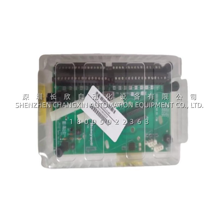
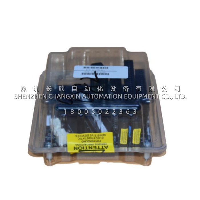
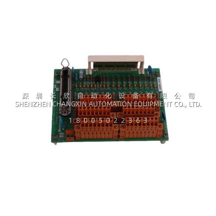
The 1SAY130130R0100​ is an ABB original equipment connection cable specifically designed for use with the ABB 07SS91 I/O communication / safety interface module, commonly found in ABB Procontic, Advant OCS, and Symphony Plus distributed control systems. One end is factory-molded with the dedicated multi-pin rectangular plug that mates precisely with the 07SS91 module’s front socket; the opposite end terminates in color-coded fly leads or a terminal-strip header for direct connection to field signal wiring, sensor loops, or expansion units. The 1SAY130130R0100​ eliminates the need to fabricate custom interface looms and guarantees correct pin assignment, shielding integrity, and mechanical retention — making it an essential MRO spare for legacy and active ABB automation cabinets.

h2 Application Scenarios

Imagine a pulp & paper mill still running an ABB Advant OCS rack with several 07SS91 communication modules linking remote I/O stations on the wet end. During a routine cabinet cleanup, a technician discovers that the original hand-made interface cable to one 07SS91 has brittle insulation and a loose crimp on pin 14 — a latent cause of intermittent loss of the “Remote I/O Healthy” signal that previously triggered unexplained line stops. The maintenance team sources and installs the 1SAY130130R0100, which clicks positively into the 07SS91 socket and lands on the existing terminal strip with zero rewiring of field cores. The factory-pinned plug removes any doubt about wire-to-pin mapping, and the robust PVC jacket withstands the humid, mildly corrosive atmosphere of the machine room. Post-replacement, the intermittent fault vanishes permanently. This example shows how the 1SAY130130R0100​ solves two pain points: it prevents misconnections that cause elusive signal drop-outs, and it restores original-spec cabling integrity in aging panels where homemade jumpers have degraded.

h2 Parameter

Main Parameters Value/Description
Product Model 1SAY130130R0100​ (Associated Module: 07SS91)
Manufacturer ABB (ABB Industrial Automation / Discrete Automation)
Product Category Pre-Assembled Module Interface Connection Cable
Designed For ABB 07SS91 I/O Communication / Safety Interface Module (Procontic / Advant / Symphony)
Cable Length 2.0 m (standard; ±0.1 m tolerance) (Cabinet-interior point-to-point reach)
Connector Type (Module End) Factory-molded rectangular multi-pin plug — keyed & locking to 07SS91 socket
Termination (Field End) Color-coded fly leads / terminal header for DIN-rail terminal block landing
Conductor Material Stranded annealed copper (multi-core, signal + shield pairs per 07SS91 definition)
Insulation / Jacket PVC (flame-retardant, abrasion-resistant)
Rated Voltage 300 V AC/DC
Operating Temperature -20 °C to +70 °C (cabinet environment)
Shielding Select pairs individually or collectively shielded (per ABB 07SS91 signal spec)
Compliance CE, RoHS, IEC 60754 low-smoke halogen-free option on later batches


h2 Technical Principles and Innovative Values

  • Innovation Point 1 — Factory-Pinned Dedicated Interface Eliminates Homemade Looms and Pin-Out Errors:​ The 1SAY130130R0100​ is produced to ABB’s exact 07SS91 pin-map. Unlike generic multi-core cables where each wire must be manually assigned, this assembly guarantees correct signal routing (digital inputs, analog loops, comms pairs, shield drains) the moment it is plugged in — removing the #1 cause of commissioning errors on legacy Procontic racks.
  • Innovation Point 2 — Controlled Impedance Signal Pairs with Drain-Wire Shielding for Noise Immunity:​ Critical signal and communication pairs inside the 1SAY130130R0100​ are twisted and drained to the shield per the 07SS91 interface standard, providing measurable improvement in noise rejection compared to untwisted equipment wire — especially important in cabinets sharing space with VFDs or contactor coils.
  • Innovation Point 3 — Keyed Locking Plug with Positive Retention Prevents Accidental Disconnection:​ The molded connector incorporates a mechanical latch that locks into the 07SS91 module bezel. This prevents the cable from working loose under panel-door vibration or during routine cabinet access — a frequent failure mode of friction-fit or screw-terminal-only jumpers in older installations.


h2 Application Cases and Industry Value

Case Study — Petrochemical Plant DCS I/O Rack Refurbishment:A refinery’s ABB Advant OCS system experienced sporadic “I/O Timeout” alarms on one process area traced to a corroded, shop-made interface cable on a 07SS91 module. The site replaced all three 07SS91 interface cables in that rack with genuine ABB 1SAY130130R0100​ leads during a turnaround. Post-startup, timeout alarms on that node dropped to zero across 12+ months of operation. The instrument engineer noted that the color-coded fly leads accelerated termination onto the marshalling terminal block by ~40 % versus the previous unmarked wires, and the locking plugs gave the team confidence the connections would stay put through thermal cycling. The 1SAY130130R0100​ directly contributed to improved DCS communication stability and reduced troubleshooting man-hours.

ABB 1SAY130010R0010 SDCS-CON-2/4 Control Card: Executes Armature / Field Regulation & Sequence Logic缩略图

ABB 1SAY130010R0010 SDCS-CON-2/4 Control Card: Executes Armature / Field Regulation & Sequence Logic

ABB 1SAY130010R0010 SDCS-CON-2/4 Control Card: Executes Armature / Field Regulation & Sequence Logic插图


Description:

The ABB 1SAY130010R0010​ is the commercial ordering reference for ABB’s SDCS-CON-2 / SDCS-CON-4 main control card (also cross-listed as SDCS-CON-2 3ADT303100R1001 / 3ADT303100R0011 depending on revision) used in ABB DCS400, DCS500 (B-version), and DCS600 series DC drive / rectifier systems. It is the “brain” of the drive — containing a 16-bit (or 32-bit in later CON-4 variants) microprocessor, program Flash, parameter RAM/EEPROM, DDCS (Distributed Digital Control System) link interface, and local digital I/O for start/stop, enable, and status feedback. The 1SAY130010R0010​ executes the armature/field regulation algorithms, processes operator-panel commands, and communicates with host PLCs via serial (RS-232/485) or fieldbus adapter modules plugged into the DDCS port.

Application Scenarios:

A steel wire-drawing line driven by an ABB DCS500B 4-quadrant DC drive suddenly went offline with a “CONTROL BOARD FAIL / NO DISPLAY” symptom — the drive’s operator panel was dark although 24 V DC auxiliary power measured correct. Technicians confirmed the panel itself was functional by testing on a neighboring drive, narrowing the fault to the ABB 1SAY130010R0010 (SDCS-CON-2)​ control card. A pre-verified spare was installed, the DIP-switch settings were copied from the failed unit (node address, fieldbus type, regulator options), and the drive booted normally, loading its previously stored parameter set from the onboard EEPROM. Production resumed the same shift, avoiding an estimated 6-hour delay in rewinding and re-stringing the line. The 1SAY130010R0010​ directly solved the critical pain point of a “dead” DC drive — when this control card fails, the entire rectifier is inoperative, making it the single most important spare part for any plant running ABB DCS-series DC drives.

Parameter:

Main Parameters Value/Description
Product Model 1SAY130010R0010​ (SDCS-CON-2 / SDCS-CON-4 compatible — verify revision)
Manufacturer ABB (Drives / Motion Division)
Product Category DC Drive Main Control Card / CPU Board (SDCS Series)
Compatible Drives ABB DCS400, DCS500 (B-version), DCS600 DC Drive / Rectifier Units [confirm frame size & BOM before order]
Microprocessor 16-bit (CON-2) or 32-bit (CON-4 variant) — firmware-dependent
Memory Program Flash + Parameter EEPROM / NVRAM (retains drive parameters on power loss)
Local I/O Start / Stop / Enable DI; Ready / Fault DO; typically 3 DI + 2 DO on-card
Communication DDCS link (to ACH/ACO panel or DDCS adapter for Profibus / Modbus / DeviceNet); RS-232/485 service port
Display 7-segment LED (shows fault codes / parameter group numbers on CON-2)
Configuration DIP switches for node address, fieldbus type, regulator options; parameter download via DriveWindow or panel
Supply Voltage Derived from drive internal 5 V / ±15 V backplane (no external supply needed when installed)
Coating / Protection Conformal coated PCB (industrial grade); IP00 (installed inside drive enclosure)
Operating Temp. -10 °C to +50 °C (inside drive cabinet; derate above 40 °C per manual)
Dimensions (approx.) 185 × 115 × 30 mm (form factor varies slightly CON-2 vs CON-4)


Technical Principles and Innovative Values:

The ABB 1SAY130010R0010 (SDCS-CON-2/CON-4)​ is engineered as a deterministic regulator and sequencer for thyristor-based DC drives.

  • Innovation Point 1 — Integrated Armature + Field Regulation in One Processor:​ The onboard micro executes both the armature-current / speed PI loops and the field-current / field-weakening control, with automatic changeover between constant-torque and field-weakening regions. This eliminates the need for a separate field controller in most 4-quadrant applications and ensures tight coordination between armature firing angle and field excitation.
  • Innovation Point 2 — Parameter Retention via Onboard NVRAM/EEPROM:​ Drive configuration (motor data, PI tunings, I/O assignments, ramp times) is stored in non-volatile memory on the 1SAY130010R0010. A replacement board can be pre-loaded offline or will adopt the stored parameters of the old unit (depending on version) — minimizing recommissioning time after a swap.
  • Innovation Point 3 — DDCS Bus Architecture for Seamless HMI & Fieldbus Extension:​ The control card’s DDCS port connects natively to ABB operator panels (ACH550/ACS-CP/ACO) or to DDCS-to-fieldbus gateways (RDIO / RDCU adapters for Profibus DP, Modbus RTU/TCP, DeviceNet). This lets the same 1SAY130010R0010​ serve both stand-alone machines and networked multi-drive systems without hardware changes — only the plug-in adapter differs.


Application Cases and Industry Value:

Case — Plastic Film Extrusion Line DC Main Drive Recovery:​A cast-film extrusion line’s 250 kW main extruder was controlled by an ABB DCS500B drive. After a capacitor-bank failure upstream caused a severe DC-bus transient, the drive would not initialize — the ABB 1SAY130010R0010 (SDCS-CON-2)​ had suffered damage to its logic-section regulator ICs. The plant’s stores held a matched-revision spare; after swapping the card and replicating DIP settings, the drive reloaded parameters from EEPROM and passed self-test. Line start-up occurred within 25 minutes of the fault being identified. The plant engineer credited having the correct 1SAY130010R0010​ on the critical-spare list — alongside thyristor fuses and cooling fans — with avoiding a half-day production loss worth >$15,000, while also eliminating the need for an emergency on-site service call.

ABB 1SAY130010R0010​ PCB Assembly: Multilayer Backplane Interface with Gold-Plated Connectors缩略图

ABB 1SAY130010R0010​ PCB Assembly: Multilayer Backplane Interface with Gold-Plated Connectors

ABB 1SAY130010R0010​ PCB Assembly: Multilayer Backplane Interface with Gold-Plated Connectors插图


Description

The 1SAY130010R0010​ is an internal Board Assembly / Interface Circuit Board manufactured by ABB, part of the ABB 800xA / Advant / S800 I/O ecosystem. It functions as a communication or signal-conditioning interface between the system backplane and associated I/O or processing modules—providing bus bridging, electrical isolation, and sometimes local analog/digital signal preprocessing—for continuous 24/7 operation in process automation and power-generation plants.


Application Scenarios

Consider a large combined-cycle power plant running ABB System 800xA with S800 I/O distributed across the turbine, boiler, and balance-of-plant areas. One marshalling cabinet begins showing a “Module Comms Lost” alarm on a rack serving critical HP bypass and attemperator loops. Diagnostics confirm the rack backplane is intact and I/O modules are good—the fault traces to a degraded internal interface board (1SAY130010R0010) whose onboard buffer ICs have weakened after 15+ years. Rather than replace the entire I/O rack (requiring re-termination of 100+ field wires), the instrumentation team powers down the section, removes the old assembly, installs a verified 1SAY130010R0010, and restores power. Communication is re-established within minutes, loop scan times return to spec, and the false alarm clears—no reprogramming, no rewiring. The 1SAY130010R0010​ directly resolves the legacy-spares availability gap for plants committed to extending the certified life of proven ABB control-system assets.

Parameter

Main Parameters Value/Description
Product Model 1SAY130010R0010​ (Alt. Ref: 1SAY130010-R0010)
Manufacturer ABB
Product Category Board Assembly / Interface Circuit Board (PCBA)
Associated System ABB System 800xA, Advant OCS (select racks), S800 / S900 I/O extension chassis
Function Backplane bus interface, signal buffering/conditioning, or communication bridge to I/O modules
Backplane Interface Gold-plated pin-header / edge connector to DCS/S800 rack backplane
Onboard Components SMT ICs (buffers, transceivers, ASIC), EEPROM for ID/config, status LEDs, filter capacitors
Isolation Galvanic isolation between field-side and system-side buses (typical ≥ 1.5 kV AC working)
Supply Voltage +5 V DC / +24 V DC derived from rack backplane (typ. 3–6 W consumption)
Communication / Bus Proprietary ABB backplane bus; may include RS-485 level translation or LVDS signaling per design
PCB Construction Multilayer industrial-grade FR-4 with solder mask & silk-screen; lead-free HASL or ENIG finish
Operating Temp. 0 °C to +60 °C (extended -20 °C to +70 °C on select revisions)
Mounting Edge-connector into DCS / S800 rack backplane; secured by captive screws or ejector levers
Dimensions (Approx.) 160 × 100 mm (typical; exact per ABB drawing for 1SAY13… series)
Weight (Approx.) 0.15–0.25 kg


Technical Principles and Innovative Values

  • Innovation Point 1 — Transparent Backplane Bus Bridging:​ The 1SAY130010R0010​ interfaces natively with the ABB 800xA / S800 backplane, appearing as a known node to the CPU. No changes to the I/O configuration database are required when swapping a failed board—it auto-reports its identity via onboard EEPROM, enabling true “plug-and-play” legacy maintenance.
  • Innovation Point 2 — Hardware-Level Noise Filtering & Isolation:​ Integrated RC filtering on signal lines and opto-/capacitive isolation between the backplane side and any external-facing circuits reject EMI from nearby VFDs and high-current contactors. This preserves data integrity on busy DCS networks and prevents spurious communication drops—a key differentiator vs. generic interface cards.
  • Innovation Point 3 — Revision-Matched Drop-In Form Factor:​ The assembly uses the identical mechanical footprint, mounting hole pattern, and connector pinout as the original ABB-supplied board. Technicians perform a direct remove-and-replace—no adapter plates, no wire relocation, no software download—keeping mean time to repair (MTTR) under 15 minutes in most cases.
ABB 1SAR330020R0000 CT-MFD Multifunction Time Relay — 24–240 V AC/DC, 0.1 s–100 h Delay缩略图

ABB 1SAR330020R0000 CT-MFD Multifunction Time Relay — 24–240 V AC/DC, 0.1 s–100 h Delay

ABB 1SAR330020R0000 CT-MFD Multifunction Time Relay — 24–240 V AC/DC, 0.1 s–100 h Delay插图


Description

The ABB 1SAR330020R0000​ is a CT-MFD series multifunction electronic time delay relay manufactured by ABB’s Control Products division. It provides eight selectable timing functions—including ON-delay, OFF-delay, interval, one-shot, cyclic ON/OFF, and star-delta (wye-delta) changeover—via a front-panel rotary selector and thumbwheel/time knob. With a universal wide-range supply of 24–240 V AC/DC and a 16 A SPDT (Form C) output contact in a 22.5 mm DIN-rail housing, it is the standard drop-in replacement for pneumatic/electromechanical timers in motor control, pump sequencing, conveyor staging, and HVAC applications.

Application Scenarios

An automated bottling line in a beverage plant used three aging pneumatic time-delay relays to sequence the conveyor start-up after the main filler reached running speed—each unit required manual air-pressure adjustment and drifted with temperature changes, causing occasional jam-ups during morning warm-up. The maintenance electrician replaced all three with ABB 1SAR330020R0000 (CT-MFD)​ timers, wiring them directly to the existing 230 V AC auxiliary supply in the panel. The front-panel knob was set to ON-delay mode with a 5-second stagger (3 s, 8 s, 13 s) to create a soft sequential start that prevents inrush current spikes on the 24 V DC sensor supply. The quartz-crystal time base held ±1 % accuracy through ambient temperature swings from 12 °C to 42 °C, and the green/red dual-color LEDs gave instant visual confirmation of power and timed-output state during commissioning. Since the retrofit, the line has logged zero timing-related jams over two production seasons. The lead electrician noted: “The 1SAR330020R0000​ gave us set-and-forget reliability. No more adjusting air bleed screws, and the LEDs mean we don’t need a multimeter to know if a timer fired.”

Parameter

Main Parameters Value/Description
Product Model 1SAR330020R0000​ (CT-MFD Multifunction Time Relay)
Manufacturer ABB (Control Products — CT Series / T Series Timers)
Product Category Electronic Multifunction Time Delay Relay
Supply Voltage 24–240 V AC (50/60 Hz) / 24–240 V DC, universal wide-range input
Rated Power Consumption ≤ 2.5 W
Time Range 0.1 s – 100 h, selectable via front thumbwheel + range switch (6 or 7 ranges)
Timing Functions ON-delay, OFF-delay, Flashing (cyclic ON/OFF), One-Shot (Impulse), Interval, Star-Delta Changeover, Retentive ON-delay (8 functions)
Output Contact 1 × SPDT (Form C): 1 NO + 1 NC, rated 16 A / 250 V AC (resistive), 30 V DC / 16 A
Time Accuracy ± 1 % of setting + 50 ms (quartz crystal time base)
Repeat Accuracy ± 0.2 % of setting
Indicators Green LED = supply present; Red LED = output energized
Mounting 35 mm DIN rail (TH35), 22.5 mm (0.89″) width, EN 50022
Operating Temp. -25 °C to +55 °C (-13 °F to +131 °F)
Storage Temp. -40 °C to +80 °C
Protection IP20 (terminals / front), IP40 (housing); pollution degree 2
Standards / Certifications IEC 61812-1, CE, UL listed, CSA, CCC, GL (Germanischer Lloyd marine optional)
Electrical Life ≥ 100,000 operations at rated resistive load
Mechanical Life ≥ 20,000,000 operations


Technical Principles and Innovative Values

The ABB 1SAR330020R0000​ replaces imprecise mechanical or pneumatic timers with microprocessor-controlled timing:

  • Innovation Point 1 — Eight Timing Functions in One Device:​ Rather than stocking separate ON-delay, OFF-delay, flasher, and star-delta timers, the 1SAR330020R0000​ consolidates all eight common functions into one SKU. The function is selected by a clearly labeled front rotary switch—no software, no DIP blocks, no tools—making it ideal for panels where future logic changes are unknown at design time.
  • Innovation Point 2 — Quartz-Crystal Time Base with ±1 % Accuracy:​ Unlike air-dashpot timers that drift with humidity and age, the CT-MFD uses a quartz-referenced digital counter. This delivers laboratory-grade repeatability (±0.2 % repeat accuracy) and immunity to temperature-induced drift across the full -25 °C to +55 °C operating range.
  • Innovation Point 3 — Universal AC/DC Wide-Range Supply:​ The internal switched-mode power stage accepts anything from 24 V DC battery systems to 240 V AC mains without jumpers or voltage-selection plugs. A single spare 1SAR330020R0000​ covers both 24 V DC control panels and 110/230 V AC MCCs—halving the number of timer spares a plant must stock.
  • Innovation Point 4 — Direct-Drive 16 A Contact & Dual-Color LED Diagnostics:​ The 16 A AgNi contact can directly switch small contactor coils, solenoid valves, or indicator beacons—eliminating intermediate interposing relays in many circuits. Front-panel green (power) and red (output active) LEDs allow technicians to confirm supply presence and timed-output state at a glance, accelerating troubleshooting during live operation.
ABB 1SAP140500R3160 EC581-ARCNET Control CPU: IEC 61131-3Compliant, 0.05 ms/1k Instructions, IP20缩略图

ABB 1SAP140500R3160 EC581-ARCNET Control CPU: IEC 61131-3Compliant, 0.05 ms/1k Instructions, IP20

ABB 1SAP140500R3160 EC581-ARCNET Control CPU: IEC 61131-3Compliant, 0.05 ms/1k Instructions, IP20插图


Description:

The ABB 1SAP140500R3160, commercially designated as the EC581-ARCNET, is a high-performance Central Processing Unit (CPU) module belonging to ABB’s AC500 series of Programmable Logic Controllers (PLCs). Distinguished from standard AC500 CPUs by its integrated ARCNET (Attached Resource Computer NETwork) token-bus interface, this module is purpose-built for applications requiring deterministic, high-speed peer-to-peer communication with distributed I/O stations, legacy machine networks, or multi-CPU synchronization—particularly in printing, packaging, and continuous-process industries.

Application Scenarios:

Consider a high-speed web-fed printing press originally commissioned in the late 1990s, where the folder, inker, and dryer sections are linked via an ARCNET token-bus network to synchronize timing across eight drive nodes. When the original AC500 CPU suffered a hardware fault, the plant discovered that a standard Ethernet-only CPU could not replace it—the ARCNET backbone would remain dark. The maintenance team sourced the ABB 1SAP140500R3160 (EC581-ARCNET)​ as a direct like-for-like swap. After transferring the application from the SD card backup and setting the ARCNET node address via DIP switches, the press resumed full communication within minutes. The built-in LCD display allowed technicians to verify I/O status locally without a laptop—a critical advantage during night-shift recoveries. This module’s unique value lies in preserving legacy ARCNET infrastructure while delivering modern PLC processing power, saving the cost of a full network retrofit.

Parameter:

Main Parameters Value/Description
Product Model 1SAP140500R3160​ (EC581-ARCNET)
Manufacturer ABB Automation (Switzerland / Sweden)
Product Category AC500 Series PLC Central Processing Unit (CPU) with ARCNET Interface
Supply Voltage 24 V DC (Range 18 – 30 V DC), reverse-polarity protected
Program Memory 256 KB Flash EPROM (non-volatile user program)
Data Memory 288 KB (incl. retentive / battery-backed RAM)
Expansion Storage SD card slot (program backup, data logging, recipe storage)
Local I/O Capacity Max. 10 expansion modules; up to 320 DI / 240 DO, 160 AI / 160 AO
Execution Speed 0.05 ms / 1,000 Boolean instructions (typical)
Communication Ports 1 × ARCNET (2.5 Mbps token bus), 2 × RS232/485 (Modbus RTU/ASCII, CS31), 1 × USB (prog.), 1 × FBP (Field Bus Plug)
Display / Indicators Integrated 1-line LCD + 8 function keys; RUN / ERR / ARCNET status LEDs
Real-Time Clock Yes (battery-backed)
Operating Temp. 0 °C to +60 °C (some refs cite –25 °C to +60 °C for wide-temp variants)
Mounting Method 35 mm DIN rail (TH35-15 per IEC 60715)
Dimensions (approx.) 76 × 62 × 127 mm (W × H × D); Weight ≈ 0.16–0.22 kg
Certifications CE, cULus, DNV, GL, BV, RoHS-compliant


Technical Principles and Innovative Values:

  • Innovation Point 1: Native ARCNET Token-Bus Determinism.​ Unlike Ethernet-based CPUs with variable latency, the ABB 1SAP140500R3160​ embeds a hardware ARCNET controller that guarantees deterministic token passing and bounded message delivery times—essential for multi-axis synchronization and legacy distributed I/O刷新 where jitter is unacceptable.
  • Innovation Point 2: Standalone Local Diagnostics via Integrated LCD.​ The front-panel alphanumeric LCD and navigation keys on the EC581-ARCNET​ allow technicians to view CPU status, force I/O bits, read error codes, and monitor process values without a PG/PC—dramatically reducing MTTR in plants where engineering laptops are not permitted on the floor.
  • Innovation Point 3: SD-Card Based Application Portability.​ The onboard SD slot permits the entire user application, symbol table, and retentive data to be cloned or restored in seconds. When swapping a failed 1SAP140500R3160, inserting the pre-loaded card auto-boots the new CPU—no download session required, which is invaluable during emergency change-outs.
ABB 1N1346 Standard Recovery Rectifier Diode — 12A 600V Stud Mount Silicon Power Diode缩略图

ABB 1N1346 Standard Recovery Rectifier Diode — 12A 600V Stud Mount Silicon Power Diode

ABB 1N1346 Standard Recovery Rectifier Diode — 12A 600V Stud Mount Silicon Power Diode插图

Description:

The 1N1346​ is an ABB / former Westinghouse / International Rectifier heritage standard-recovery silicon rectifier diode housed in a threaded stud-mount package (typically DO-4 / DO-5 / DO-203AB style). Rated at 12 A average forward current and 600 V peak reverse voltage, it is designed for general-purpose AC-to-DC rectification, free-wheeling, DC link blocking, and snubber diode duties in industrial drive power sections, welding machines, battery chargers, and vintage control-circuit power supplies where fast-recovery (FRD) characteristics are not required.h2 Application Scenarios:A steel service center still operating a 1980s vintage DC drive-controlled bar shear was experiencing erratic DC bus regulation and occasional fuse blowing on the three-phase bridge rectifier feeding the armature circuit. Visual inspection revealed one of the six original stud-mounted rectifiers had cracked and the anode lead had oxidized. The OEM part cross-referenced to the 1N1346. The maintenance electrician removed the faulty diode—undoing the 10-32 stud nut and two ring-terminal screws—cleaned the mating surfaces with fine emery cloth, applied a thin layer of thermal compound, torqued the new 1N1346​ to spec, and reconnected the leads. The drive powered up cleanly; DC bus ripple returned to within original design limits and the intermittent overcurrent trips ceased. The plant’s drive specialist commented that having the correct 1N1346​ standard-recovery diode on the shelf “saved a day of hunting for obsolete parts and kept the shear in production during peak shipping season.” This is the classic role of the 1N1346: an unsung but essential component whose correct specification—standard (not fast) recovery, appropriate VRRM, and stud-mount ruggedness—is critical when replacing originals in legacy power electronics.h2


Parameter:

Main Parameters Value/Description
Product Model 1N1346​ (also cross-listed as 1N1346A, JAN1N1346 depending on screening)
Manufacturer ABB (heritage Westinghouse / IR / SEMIKRON cross-reference)
Product Category Standard Recovery Silicon Rectifier Diode (Stud Mount)
Average Forward Current (IF(AV)) 12 A @ TC= 55 °C (case temp), derated per heatsink
Peak Reverse Repetitive Voltage (VRRM) 600 V
Forward Voltage Drop (VF) ≤ 1.1 – 1.3 V @ 12 A (typical for silicon standard recovery)
Reverse Leakage Current (IR) ≤ 1 mA @ VRRM, 25 °C
Non-Repetitive Surge (IFSM) 250 – 300 A (1 cycle, 60 Hz sine)
Recovery Time (trr) Standard recovery (~ 3 – 5 µs typical; NOT a fast-recovery diode)
Package Style DO-5 / DO-203AB — threaded stud (¼–28 UNF typical) + two solder / pressure tabs or axial leads per variant
Cathode / Anode Identification Stud = Cathode (on most 1N1346; stud = Anode on “R” variants — verify marking)
Operating Junction Temp. -65 °C to +175 °C
Mounting Torque 8 – 12 in-lb (0.9 – 1.4 N·m) on stud nut; use thermal grease for heatsink mating
Qualification / Screening Commercial / JAN / JANTX available per vintage batch
Key Note Match polarity (stud cathode vs. stud anode) to the removed unit before installation


h2 Technical Principles and Innovative Values:

  • Innovation Point 1 — Robust Diffusion-Junction Silicon Design for High Surge Withstand.​ The 1N1346​ employs a diffused p-n junction optimized for standard-recovery rectification rather than fast switching, giving it excellent tolerance to high non-repetitive surge currents (up to 250 A+ for a half-cycle). This makes it ideal for line-frequency bridge rectifiers where momentary inrush from capacitive DC-link charging or transformer magnetizing current would destroy a smaller signal diode.
  • Innovation Point 2 — Threaded Stud Mounting for Low Thermal & Electrical Resistance.​ Unlike press-fit or surface-mount diodes, the 1N1346​ mounts via a ¼–28 UNF threaded stud directly into a tapped hole or through-bolted with nut on a machined heatsink. Properly torqued with thermal compound, this provides a low-ohmic path for both heat (to the sink) and return current (through the stud), ensuring the diode operates within its 12 A rating even in warm cabinet environments.
  • Innovation Point 3 — MIL-Spec Heritage & Cross-Industry Interchangeability.​ Originally qualified to MIL-SPEC (JAN / JANTX classes), the 1N1346​ remains backward-compatible with countless legacy drive, welder, and plating-rectifier designs. It directly replaces 1N1190, 1N1202, and many OEM-specific stud diodes of equivalent VRRM/ IF, making it a versatile single-part inventory item for plants maintaining mixed-vintage equipment.

h2 Application Cases and Industry Value:Case — Plating Shop 3-Phase Bridge Rectifier Overhaul:​ An electroplating line used a 500 A 12 V DC rectifier built from six stud-mounted diodes in a full-wave bridge. Two diodes failed after 15 years of continuous duty. The original OEM part was discontinued; cross-reference pointed to the ABB 1N1346​ (12 A rating sufficient for the control / pilot supply bridge of the regulator, not the main 500 A stack—those used larger 1N3208-class units). The control bridge was rebuilt with six new 1N1346​ diodes, restoring the automatic voltage-regulation reference circuit. The plating shop supervisor noted that “the reference was rock-steady again—no more wandering bath voltage,” and the 12-per-diode spend prevented a 4,000 new rectifier controller purchase.

ABB 1MRK002247-ARR01 ARR01 Module – Analog Input / Signal Conditioning Board for RELION & 1MRK Racks缩略图

ABB 1MRK002247-ARR01 ARR01 Module – Analog Input / Signal Conditioning Board for RELION & 1MRK Racks

ABB 1MRK002247-ARR01 ARR01 Module – Analog Input / Signal Conditioning Board for RELION & 1MRK Racks插图


Description:

The ABB 1MRK002247-ARR01​ (designated ARR01 in the 1MRK I/O family) is an Analog Input / Signal Conditioning Module implemented as a printed circuit board for ABB RELION®-series protection and control IEDs, bay controllers, and compatible 1MRK substation automation racks. It accepts low-level analog field signals—such as 4–20 mA transducer outputs, ±10 V DC, or mA signals from DC transducers—provides galvanic isolation and programmable gain/offset linearization, then delivers digitized process values to the host IED over the internal backplane bus for use in metering, control-loops, and SCADA reporting.


Application Scenarios:

Picture a 220 kV bulk-oil transformer monitoring station where the existing analog board feeding winding-temperature RTD-converted 4–20 mA signals to the bay controller begins to drift, causing the SCADA system to log false overtemperature alarms. The instrument engineer identifies the 1MRK002247-ARR01​ as the source. During a planned short outage, the old module is withdrawn from the I/O extender slot, field wires (shielded twisted pair with separate drain) are transferred to the new screw terminals, and a fresh 1MRK002247-ARR01​ is seated. On power-up the module passes its self-calibration, the green OK LED illuminates, and the temperature readings stabilize within ±0.2 °C of the reference thermometer. Because the 1MRK002247-ARR01​ incorporates input-side RC filtering and 2.5 kV galvanic isolation, it rejects the electrical noise from nearby 220 kV disconnector operations that previously corrupted the analog values. The key pain point solved: a direct-form-fit analog interface replacement that restores measurement accuracy and noise immunity without disturbing the IED main unit, CT/VT wiring, or protection settings—keeping the bay compliant with grid-code monitoring requirements.


Parameter:

Main Parameters Value/Description
Product Model 1MRK002247-ARR01​ (ARR01 Series)
Manufacturer ABB (Sweden / Switzerland)
Product Category Analog Input / Signal Conditioning Module (1MRK I/O Family)
System Compatibility ABB RELION® 650 / 670 Series (REF670, RET670, RED670, REB670) with 1MRK I/O extender; select SPAC / SPA systems
Input Channels 4 or 8 independent analog inputs (typical; verify original board label — ARR01 commonly 4-ch precision version)
Input Signal Types 4–20 mA (active / passive loop), 0–10 V DC, ±10 V DC, 0–20 mA (jumper or software selectable per channel on most revisions)
A/D Resolution 12-bit or 16-bit successive-approximation ADC (dependent on host IED firmware version)
Accuracy ±0.2 % of full scale (typical @ 25 °C), ±0.5 % over full temp. range
Isolation ≥ 2.5 kV AC input-to-backplane galvanic isolation per channel group
Input Impedance ≈ 250 Ω (4–20 mA mode) / > 100 kΩ (voltage mode)
Update / Scan Time 20–100 ms per channel (synchronous with IED task cycle)
Indicators Green PWR/OK LED + per-module Health indicator; channel activity reflected in IED diagnostics
Supply / Backplane 24 V DC from system backplane or carrier (≤ 3 W consumption)
Mounting I/O extender slot or DIN-rail carrier in ABB bay controller chassis; screw-terminal field wiring
Operating Temp. -25 °C to +70 °C (storage: -40 °C to +85 °C); 5–95 % RH non-condensing
Certifications CE, IEC 60255 / IEC 61000-6-2 (as component of host system), RoHS


Technical Principles and Innovative Values:

The 1MRK002247-ARR01​ is a substation-qualified analog front-end, not a generic DAQ card. It is designed to survive the electromagnetic environment of EHV switchyards while delivering metrology-grade process values.

  • Innovation Point 1: Galvanically Isolated Per-Group Analog Front-End with Input Filtering.​ Each analog input group on the 1MRK002247-ARR01​ passes through an instrumentation amplifier, active anti-aliasing RC filter (cutoff typically 15–20 Hz), and an isolation barrier before reaching the A/D converter. This topology rejects common-mode noise from switchyard earth-potential rise (EPR) events and 50/60 Hz pickup on long sensor cables—critical when measuring low-level process signals in electrically noisy environments.
  • Innovation Point 2: Host-Synchronized Sampling Aligned to Protection Task Cycles.​ Unlike stand-alone data-acquisition modules that sample asynchronously, the 1MRK002247-ARR01​ is clocked by the host IED’s backplane and synchronizes its conversion cycle with the protection/control task. This eliminates jitter between analog measurement updates and the control-loop execution, making it suitable for closed-loop applications such as tap-changer voltage regulation or PSS (Power System Stabilizer) auxiliary inputs.
  • Innovation Point 3: Form-Fit Drop-In with Auto-Configuration.​ On insertion into a compatible 1MRK extender, the 1MRK002247-ARR01​ is auto-detected by the IED firmware. Channel ranges, engineering-unit scaling, and alarm thresholds are already defined in the downloaded setting file—no DIP-switch changes required. For maintenance teams this means a failed analog board is swapped in under 10 minutes with zero re-engineering, and the IED immediately resumes reporting accurate process data.
ABB 1MRK002247-AH Measurement Board: Burden-Optimized CT/VT Inputs with Galvanic Isolation缩略图

ABB 1MRK002247-AH Measurement Board: Burden-Optimized CT/VT Inputs with Galvanic Isolation

ABB 1MRK002247-AH Measurement Board: Burden-Optimized CT/VT Inputs with Galvanic Isolation插图

Description

The ABB 1MRK002247-AH​ is an internal Current / Voltage Transformer (CT/VT) analog input conditioning module—also referred to as a measurement or analog front-end board—designed for installation inside ABB REx670 series numerical protection and control IEDs (REG670, REL670, RET670, REC670). It receives secondary currents from protective CT cores (typically 1 A or 5 A) and secondary voltages from VT/PT secondaries (typically 100 V / 110 V line-to-line or 57.7 V phase-to-neutral), scales and filters them, and presents precision analog signals to the relay’s main A/D conversion stage. The 1MRK002247-AH​ typically supports six CT inputs and two to four VT inputs depending on the relay variant and is a fundamental component for accurate phasor measurement, metering, fault recording, and protection-element operation.h2 Application ScenariosImagine a 220 kV transmission substation where an ABB REG670 distance-protection relay begins reporting slightly skewed apparent-power values and occasional “Metering Channel Error” self-test warnings after years of service. Ratio checks confirm the primary CT/VT secondaries are correct—the issue is traced to aging burden resistors and filter capacitors on the internal analog-input board. Rather than replace the entire IED (which would necessitate reloading the SCL configuration, re-verifying protection settings, and scheduling a protection outage), the protection engineer sources a version-matched ABB 1MRK002247-AH (AH revision). With the DC and VT supplies isolated, the relay lid is opened, the old PCB is disconnected from its backplane header and standoffs, and the new 1MRK002247-AH​ is seated. On power-up the relay passes all self-tests; magnitude and phase-angle accuracy return to specification with no re-calibration required. This scenario illustrates the 1MRK002247-AH‘s vital function: it is the precision gateway between the switchyard analog world and the digital protection algorithm, and a targeted board swap restores measurement fidelity without disturbing commissioned logic.h2


Parameter

Main Parameters Value/Description
Product Model 1MRK002247-AH​ (AH Revision)
Manufacturer / Origin ABB / Switzerland (CH)
Product Category Internal CT / VT Analog Input Conditioning Module (Measurement Board)
Compatible Host Devices ABB REx670 series IEDs (REG670, REL670, RET670, REC670 — confirm host type & rear-slot layout)
CT Input Channels 6 × independent CT inputs (1 A or 5 A nominal secondary; selectable via host configuration / hardware jumper in some variants)
VT / PT Input Channels 2 × 3-phase VT (line-to-line 100/110 V) or 4 × VT (phase-to-neutral 57.7/63.5 V) — variant-dependent
Rated CT Burden ≤ 0.1 VA / ≤ 0.2 VA per phase (low-burden design to minimize CT saturation influence)
Frequency Range 50 / 60 Hz ± 5 Hz (extends to harmonic measurement range per relay firmware)
Isolation Galvanic isolation between analog inputs, logic section, and backplane (typ. ≥ 2000 V RMS test)
Analog Bandwidth DC to ≈ 2 kHz (covers fundamental + 2nd–5th harmonic for some protection elements)
Connectors Multi-pin header / card-edge to motherboard + screw-terminal or plug-in field terminals (host-dependent)
Operating Temperature -20 °C to +70 °C (per host IED specification)
Mounting Method Plug-in mount on internal chassis / motherboard inside REx670 relay housing


*Note: Exact CT/VT channel count, 1 A / 5 A selection method, and terminal block type must be verified against the removed board photo and host device nameplate before ordering.h2 Technical Principles and Innovative ValuesThe 1MRK002247-AH​ is a precision analog front-end—not a standalone meter—engineered to stringent protection-class accuracy requirements.

  • Innovation Point 1 – Low-Burden Wide-Range CT Inputs: The 1MRK002247-AH​ uses precision shunt resistors and active buffering to present a very low burden (≤ 0.1–0.2 VA @ 1 A / 5 A) to the CT secondary. This minimizes the risk of CT saturation during high-fault currents and preserves waveform fidelity for sensitive elements such as sensitive directional comparison and harmonic restraint functions.
  • Innovation Point 2 – Anti-Aliasing Filtering with Phase-Shift Compensation: Each CT and VT channel incorporates a 2nd-order analog low-pass filter (fc ≈ 1.5–2 kHz) to prevent aliasing before A/D sampling, followed by digital phase-angle compensation in the relay firmware. This dual-stage approach yields Class 0.5 / Class 1 metering accuracy and ≤ ±0.5° phase error across the rated frequency band—critical for distance protection reach accuracy.
  • Innovation Point 3 – Transparent Swap with Auto-Calibration Recall: All ratio, vector-group, and phasor-correction coefficients are stored in the relay CPU’s non-volatile memory—not on the 1MRK002247-AH. On replacement, the relay performs an automatic self-calibration / sanity check at power-up and applies the saved correction factors, so measurement accuracy is restored without manual recalibration or re-entry of CT/VT ratios.
ABB 1MRK002247-AGR05 PC Board – AGR05 Processor & Communication Module for 670 Series Relays缩略图

ABB 1MRK002247-AGR05 PC Board – AGR05 Processor & Communication Module for 670 Series Relays

ABB 1MRK002247-AGR05 PC Board – AGR05 Processor & Communication Module for 670 Series Relays插图


Description:

The ABB 1MRK002247-AGR05, also identified as the AGR05 Processor & Communication Module (PCM), is a core control board designed for ABB 670-series protection and control terminals (RED670, REC670, REL670, etc.). It houses the main CPU, RAM/Flash memory, dual Ethernet ports, serial communication interfaces, and protocol stacks (IEC 61850, IEC 60870-5-103/104, DNP3, Modbus RTU/TCP), serving as the central intelligence and substation communication gateway for the relay rack.

Application Scenarios:

A regional transmission utility operating a 400 kV substation experienced a boot failure on one bay’s RED670 terminal after a lightning-induced surge on the station service supply damaged the AGR-type processor board — the ABB 1MRK002247-AGR05. The protection elements themselves (current/voltage inputs on separate AIN boards) were intact, but the terminal could no longer communicate with the SCADA or execute the application logic. The relay engineer powered down the rack, extracted the faulty AGR05 board, inserted a pre-loaded replacement 1MRK002247-AGR05​ with the same firmware version and configuration file (pre-staged via PCM-Card or laptop), reseated it, and rebooted. Within minutes the RED670 was back online — all IEC 61850GOOSE subscriptions re-established and the bay returned to full protection and control service. This case highlights the critical role of the 1MRK002247-AGR05​ as the “brain and voice” of the 670-series IED, and why having a compatible spare (with matching firmware) is essential for rapid recovery in substation automation.

Parameter:

Main Parameters Value/Description
Product Model 1MRK002247-AGR05​ (AGR05 Processor & Communication Module / PCM)
Manufacturer ABB
Product Category Processor / Communication Board (PCM) for 670 Series Protection & Control Terminals
Compatible System ABB RED670, REC670, REL670, RET670, REM670 (670-series rack-mount IEDs)
CPU 32-bit / RISC processor with onboard SDRAM & Flash (capacity per firmware revision)
Communication Ports 2 × 10/100 Mbps Ethernet (RJ-45, IEC 61850, Modbus TCP), 1 × RS-232/485 Service Port, 1 × Front USB/mini-D (config/download)
Supported Protocols IEC 61850 Ed.1 & Ed.2 (GOOSE, MMS), IEC 60870-5-103, IEC 60870-5-104, DNP3 (serial & TCP), Modbus RTU & TCP
Memory Non-volatile Flash for application & config; battery-backed or super-cap SRAM for event/oscillography buffers (per rack PSU)
Supply Voltage 24 V DC / 48 V DC / 110 V DC or 230 V AC (via rack power supply module — board draws from backplane)
Status Indication RUN, ERR, COM1, COM2 LEDs on front face
Operating Temperature -25 °C to +55 °C (IEC 60255-6 class)
Storage Temperature -40 °C to +85 °C
Humidity 5 %–95 % RH, non-condensing
Mounting Method Insert into dedicated PCM slot of 670-series rack backplane, secured by fixing screw/latch
Protection Class IP20 (for enclosed cubicle installation)
Dimensions (approx.) 233 × 115 × 22 mm (L × W × H, PWA only)
Weight (approx.) 0.25–0.35 kg


Technical Principles and Innovative Values:

  • Innovation Point 1 — Integrated CPU + Dual-Stack Communication Engine.​ The ABB 1MRK002247-AGR05​ combines a high-performance processor with dual independent Ethernet MACs and a full protocol stack suite. This allows simultaneous connection to process bus (IEC 61850 GOOSE/MMS) and station bus / SCADA (IEC 60870-5-104or DNP3) without external protocol converters — reducing bay-level complexity and single points of failure.
  • Innovation Point 2 — Seamless Firmware & Configuration Management.​ Application logic, setting groups, and GOOSE definitions reside in the AGR05’s Flash memory and can be backed up to a PCM-Card or PC. Swapping a failed 1MRK002247-AGR05​ involves loading the saved configuration via PACiS/PCM Tool or inserting a pre-programmed replacement — the board auto-boots into the application, preserving all IED identity (IP, station name, dataset bindings).
  • Innovation Point 3 — Time Synchronization & High-Resolution Event Stamping.​ The AGR05 supports IRIG-B, SNTP, and PTP (IEEE 1588) time synchronization via Ethernet or dedicated B-code input on the rack, ensuring µs-accurate time-stamping of disturbance records, sequence-of-events (SOE), and oscillography — critical for post-fault analysis in transmission networks.
ABB 1MRK002247-AG Instrument Transformer Module — 6I+6U CT/VT Signal Conditioning for Protection Relays缩略图

ABB 1MRK002247-AG Instrument Transformer Module — 6I+6U CT/VT Signal Conditioning for Protection Relays

ABB 1MRK002247-AG Instrument Transformer Module — 6I+6U CT/VT Signal Conditioning for Protection Relays插图

Description:

The ABB 1MRK002247-AG​ is an instrument Current/Voltage Transformer Module (TRM Series) manufactured by ABB for use in medium-voltage switchgear, relay protection panels, and substation control cubicles. Despite the word “transformer” in its name, it is not a power transformer but a compact, integrated auxiliary CT/VT signal-conditioning and termination module combining six current-transformer (CT) secondary channels—typically rated 1 A—and six voltage-transformer (VT/PT) secondary channels (110 V / 220 V AC, 50/60 Hz), with compression-type terminals for secure field wiring. The 1MRK002247-AG​ provides galvanic isolation, orderly marshalling of CT/PT secondaries, and a standardized interface to ABB protection relays such as the REF 600 / RET 600 / REC 600 series.h2 Application Scenarios:In a 132 kV substation undergoing a protection relay retrofit, the original relay-panel CT/PT secondary wires were a tangle of loose jumpers terminated on assorted screw-terminal strips—several had loosened over decades, causing intermittent CT-circuit opens and measurement drift on one feeder. The EPC contractor removed the scattered terminal strips and installed the ABB 1MRK002247-AG​ in their place. Six CT secondaries (1 A) and six VT secondaries (110 V) were landed on its compression terminals, producing a clean, vibration-proof connection to the new REF615 numerical relay. The 1MRK002247-AG​ eliminated loose-contact CT opens, reduced panel wiring complexity, and gave the utility a standardized, serviceable interface for future relay changes. This illustrates the core value of the 1MRK002247-AG: it turns a chaotic protection-panel secondary wiring nest into a reliable, isolated, and maintainable termination point—critical for avoiding CT-secondary opens (a safety hazard) and ensuring measurement accuracy.h2


Parameter:

Main Parameters Value/Description
Product Model 1MRK002247-AG​ (TRM Series, 1 A CT version)
Manufacturer ABB (Sweden / Global — Protection & Substation Automation)
Product Category Instrument Current / Voltage Transformer Module (Aux. CT + VT Termination & Marshalling)
CT Channels 6 × Current Transformer Secondaries — Typical 1 A rated (AG suffix = 1 A; AH suffix = 5 A)
VT Channels 6 × Voltage Transformer Secondaries — 110 V / 220 V AC, 50/60 Hz (typical protective VT secondary)
Isolation Voltage ≥ 2 kV AC (between primary-side field circuits and secondary / relay side per IEC 60255)
Terminal Type Compression / crimp lug terminals — Vibration-resistant, preferred over screw terminals in switchgear
Mounting Method Panel / cubicle mounting or rack-slot (depending on enclosure; also available in DIN-rail variant per local BOM)
Frequency 50 / 60 Hz
Operating Temp. -20 °C to +55 °C
Weight (Approx.) 2.5 – 3.0 kg
Related Suffixes -AH (5 A CT version), -AP / -AT (alternative terminal or ratio configs) — Verify old unit before substitution


h2 Technical Principles and Innovative Values:

  • Consolidated, Isolated CT/PT Secondary Marshalling:​ The 1MRK002247-AG​ brings six CT legs and six VT legs into one DIN-rail- or panel-mounted block with built-in isolation boundaries, replacing a handful of loose terminal strips. This reduces wiring volume, clarifies circuit tracing during troubleshooting, and prevents accidental cross-connection between phases or between CT and VT circuits.
  • Compression-Terminal Reliability in Vibrating Environments:​ Unlike screw terminals that can loosen on switchgear subject to mechanical or thermal cycling, the compression (crimp-lug) terminals used on the ABB 1MRK002247-AG​ maintain constant contact pressure—critically important for CT secondaries, where a loose connection can create a hazardous open-circuit condition.
  • Direct Compatibility with ABB Protection Relay Families:​ The module’s channel arrangement and signal levels are matched to ABB numerical relays (REF620, RET620, REC670, etc.), allowing the protection engineer to standardize panel design across multiple bays. Swapping a relay in the future requires only unplugging it from the test block / terminal—the 1MRK002247-AG​ and its field wiring stay untouched.
Back to Top

Search For Products

Product has been added to your cart