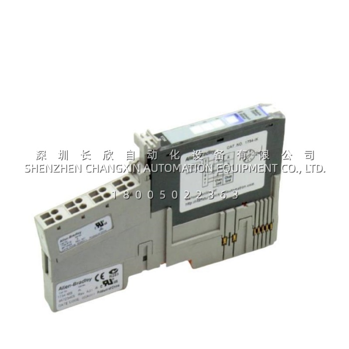
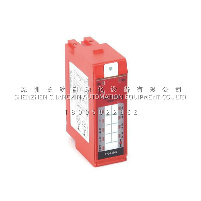
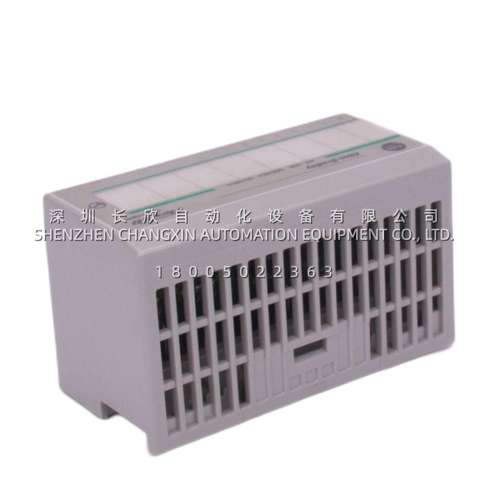
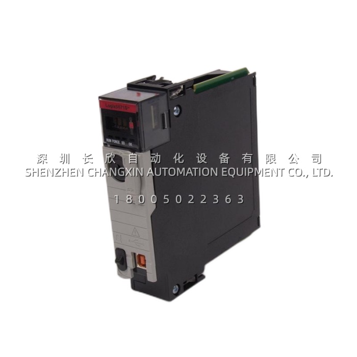
Allen‑Bradley 1761-NET-AIC​ Advanced Interface Converter – RS-232 to RS-485 for DH-485 & DF1 Networks缩略图

Allen‑Bradley 1761-NET-AIC​ Advanced Interface Converter – RS-232 to RS-485 for DH-485 & DF1 Networks

Allen‑Bradley 1761-NET-AIC​ Advanced Interface Converter – RS-232 to RS-485 for DH-485 & DF1 Networks插图


Product Overview

The Allen-Bradley 1761-NET-AIC, also marketed as the AIC+ (Advanced Interface Converter), is a compact serial communication interface device developed by Rockwell Automation to bridge RS-232 (DF1 full-duplex or half-duplex) equipment with DH-485 multi-drop RS-485 networks used by MicroLogix™ 1000/1100/1200/1500 controllers, SLC 500™ processors with DH-485 ports, and legacy PanelView™ terminals. The Allen-Bradley 1761-NET-AIC​ performs both physical layer translation (RS-232 ↔ RS-485) and electrical isolation, allowing a personal computer with a standard RS-232 COM port or USB-to-RS-232 adapter to participate in a DH-485 network for programming, monitoring, or peer-to-peer messaging—functions formerly requiring the discontinued 1747-PIC ISA card or 1747-AIC converter.The Allen-Bradley 1761-NET-AIC​ is housed in a DIN-rail-mountable enclosure and features one DB-9 female RS-232 port, one 8-pin mini-DIN RS-232 port (for direct connection to MicroLogix Channel 0), and a two-position removable screw-terminal block for the RS-485 (DH-485) network pair (Data A / Data B) plus shield. It provides 500 V AC optical isolation between the RS-232 side and the RS-485 side, breaking ground loops and improving noise immunity in electrically noisy industrial environments. Power can be drawn parasitically from certain MicroLogix processors via the mini-DIN cable (1761-CBL-AM00 or similar) or supplied externally via 24 V DC to the RS-485 terminal block—selectable by an onboard slide switch. Baud rate is set via a DIP switch (supports up to 115.2 kbps) and the unit includes per-port transmit/receive LEDs plus a power LED for immediate visual diagnostics.By enabling modern laptops and programming stations to interface with legacy DH-485 networks, the Allen-Bradley 1761-NET-AIC​ extends the service life and maintainability of installed MicroLogix and SLC 500 systems that remain prevalent in packaging machinery, material handling, and building automation applications worldwide.

Technical Specifications

Product Model | 1761-NET-AICManufacturer | Rockwell Automation / Allen-BradleyProduct Type | Advanced Interface Converter (AIC+) – RS-232 to RS-485 (DH-485 / DF1)Series | Allen-Bradley 1761 (MicroLogix Accessories)RS-232 Ports | 1 × DB-9 Female (DTE), 1 × 8-pin Mini-DIN (MicroLogix CH0 compatible)RS-485 Port | 2-position + Shield screw terminal (Data A, Data B, Shield/Drain); DH-485 half-duplexIsolation Voltage | 500 V AC RMS continuous between RS-232 side and RS-485 side (optical)Supported Protocols | DH-485, DF1 (Full-Duplex & Half-Duplex), ASCII (pass-through)Baud Rate Selection | DIP switch selectable: 300, 600, 1200, 2400, 4800, 9600, 19.2k, 38.4k, 57.6k, 115.2k bpsPower Supply Options | Parasitic from MicroLogix processor via mini-DIN cable OR external 20–28 V DC @ ≈ 50 mA (24 V DC nom.)RS-485 Termination | Onboard 120 Ω termination resistor selectable via DIP switchIndicators | PWR (green), CH1 Tx/Rx (yellow), CH2 Tx/Rx (yellow)Mounting | 35 mm DIN rail (EN 60715) snap-mountOperating Temperature | 0 °C to +60 °C (32 °F to 140 °F)Storage Temperature | -40 °C to +85 °CHumidity (non-condensing) | 5 % to 95 % RHAgency Approvals | UL Listed, cULus, CE, C-Tick, KCDimensions (H × W × D) | approx. 90 mm × 35 mm × 75 mm (3.54″ × 1.38″ × 2.95″)

Main Features and Advantages

The primary value of the Allen-Bradley 1761-NET-AIC​ is its ability to modernize access to legacy DH-485 networks without altering existing panel wiring or node addressing. Unlike a simple RS-232-to-RS-485 adaptor, the Allen-Bradley 1761-NET-AIC​ is protocol-aware in the sense that it correctly handles DH-485 token-pass behavior and DF1 framing, and its 500 V AC isolation prevents damaging ground potential differences between a laptop (earth-grounded via its power supply) and a floating or differently-referenced DH-485 network in the control panel. This isolation is critical when connecting test equipment to running machinery—a direct un-isolated connection can introduce ground loops that disrupt communications or, worse, damage port electronics on the PLC.Flexible powering is another strong point. The Allen-Bradley 1761-NET-AIC​ can be “parasite-powered” from a MicroLogix 1200/1500 Channel 0 mini-DIN port (which supplies +5 V DC), eliminating the need for a separate 24 V DC supply in simple programming-cart applications. For permanent panel installation on a DH-485 multi-drop, the unit is typically wired to the panel’s 24 V DC supply via the RS-485 terminal block, with the power-source slide switch set accordingly. This dual-power design means one spare Allen-Bradley 1761-NET-AIC​ serves both as a field technician’s portable DH-485 interface and as a fixed network node converter in OEM machinery.Built-in diagnostics simplify troubleshooting: independent yellow LEDs for each channel show when data is actively being transmitted or received, allowing technicians to confirm cable integrity and baud-rate matching at a glance. The DIP-switch-selectable 120 Ω termination resistor removes the need for an external terminating resistor at the physical ends of the DH-485 trunk. For system integrators maintaining mixed-era Rockwell networks, the Allen-Bradley 1761-NET-AIC​ effectively replaces both the 1747-PIC (obsolete PIC card) and the 1747-AIC (bulky SLC rack card) in a fraction of the panel space, while remaining fully compatible with RSLinx™ Classic’s DH-485 driver for node browsing, uploading, and downloading.

Application Field

The Allen-Bradley 1761-NET-AIC​ is most commonly deployed wherever a DH-485 network of MicroLogix or SLC 500 nodes must be accessed from a PC, HMI, or another serial device. In stand-alone packaging machines originally designed around a MicroLogix 1100 or 1200 with DH-485 networking to PanelView 300/600 terminals, the Allen-Bradley 1761-NET-AIC​ lets maintenance engineers connect a laptop via RS-232 (or via a USB-RS232 dongle) to go online for troubleshooting, recipe changes, or firmware updates—without disturbing the existing DH-485 multi-drop wiring.In legacy material handling systems—conveyor zones, sortation loops—where multiple MicroLogix 1000 processors communicate over a single DH-485 trunk, the Allen-Bradley 1761-NET-AIC​ provides the programming port interface for the site’s laptop cart. It is also used in building automation retrofits and small-process skids (water treatment, batch blending) that retain DH-485 as the field bus. OEMs often incorporate the Allen-Bradley 1761-NET-AIC​ inside their control enclosures to give end-users a standardized, isolated DH-485 access point for handheld programmers or SCADA serial interfaces.When migrating older SLC 500 systems that still use DH-485 for panel-mounted operator interfaces, the Allen-Bradley 1761-NET-AIC​ can interface those legacy HMI nodes to a newer programming PC during the transition period. For any application requiring reliable, isolated conversion between point-to-point RS-232 and multi-drop DH-485 / RS-485 half-duplex networks within the Rockwell Automation ecosystem, the Allen-Bradley 1761-NET-AIC​ remains the recommended and widely stocked solution.

Related Products

  • 1761-CBL-AM00​ — Programming cable, 8-pin mini-DIN to DB-9 null-modem; connects MicroLogix CH0 to the 1761-NET-AIC​ mini-DIN port or directly to PC.
  • 1761-CBL-PM02​ — 8-pin mini-DIN to 8-pin mini-DIN cable for connecting two MicroLogix ports or MicroLogix to 1761-NET-AIC​ (depending on application).
  • 1747-AIC​ — Older SLC 500 rack-mounted DH-485 / DF1 interface converter; functionally similar but requires a 1746 chassis slot; the 1761-NET-AIC​ is the standalone DIN-rail replacement.
  • 1747-PIC​ — Obsolete ISA-bus DH-485 interface card for PCs; the 1761-NET-AIC​ + RS-232 port is the modern substitute.
  • 1764-LRP​ / 1764-LSP​ — MicroLogix 1100 series processors that natively support DH-485 and Ethernet; often used in systems where the 1761-NET-AIC​ provides the DH-485 access port.
  • 1762-L24BWA​ / 1762-L24BXB​ — MicroLogix 1200 processors commonly networked via DH-485 through a 1761-NET-AIC.
  • 2711-K3A​ / 2711-K6C​ — PanelView Standardterminals with DH-485 communication; typical DH-485 nodes on a network accessed via the 1761-NET-AIC.
  • 1784-CP10​ — RS-232 cable (null-modem DB-9 to DB-9) sometimes used between PC COM port and the DB-9 side of the 1761-NET-AIC.
  • 9355-WAB-OEM​ — RSLinx Classic OEM software license used to browse DH-485 nodes through the 1761-NET-AIC.
Allen‑Bradley 1756-PA72K​ ControlLogix 75W AC Power Supply – 85–265V AC Input, Conformal Coated (K-Version)缩略图

Allen‑Bradley 1756-PA72K​ ControlLogix 75W AC Power Supply – 85–265V AC Input, Conformal Coated (K-Version)

Allen‑Bradley 1756-PA72K​ ControlLogix 75W AC Power Supply – 85–265V AC Input, Conformal Coated (K-Version)插图 Allen‑Bradley 1756-PA72K​ ControlLogix 75W AC Power Supply – 85–265V AC Input, Conformal Coated (K-Version)插图1


Product Overview

The Allen-Bradley 1756-PA72K​ is a 75-watt AC-input power supply module engineered for Rockwell Automation’s ControlLogix® 1756 series programmable automation controller chassis. It is designed to occupy Slot 0 (the leftmost position) of any standard 1756 chassis—including the 1756-A4, A7, A10, A13, and A17—where it converts facility AC mains (or DC in the specified range) into the multiple regulated DC voltages required by the ControlLogix backplane: 5.1 V DC for logic circuits, 3.3 V DC, 1.2 V DC, and 24 V DC for auxiliary/field power. The “K” suffix on the Allen-Bradley 1756-PA72K​ denotes that the printed circuit board assemblies have been processed with a conformal coating—a thin polymeric film that protects against moisture, salt spray, condensation, and airborne contaminants classified under ISA-S71.04G1 through G3 severity levels. This makes the Allen-Bradley 1756-PA72K​ the preferred choice for pulp & paper mills, wastewater treatment plants, coastal marine installations, and chemical processing areas where uncoated electronics would be vulnerable to premature corrosion or dendrite formation.The Allen-Bradley 1756-PA72K​ accepts a universal input range of 85–265 V AC (47–63 Hz) or 85–300 V DC, eliminating the need for voltage-select jumpers and simplifying global deployment. It delivers up to 10 A on the 5.1 V backplane rail (total 75 W maximum across all outputs) and supports Remove and Insert Under Power (RIUP) for hot-swap replacement in a running system. When higher availability is required, two 1756-PA72K units can be deployed in an N+1 redundant configuration using a 1756-RA or 1756-RM2 redundancy adapter module and the appropriate 1756-CPR2 cable set. LED status indicators on the front of the Allen-Bradley 1756-PA72K​ provide at-a-glance confirmation of AC presence (AC OK), DC output health (DC OK), and fault conditions, assisting maintenance personnel in rapid diagnostics without test equipment. Fully compatible with all Logix5000™ controllers and 1756 I/O/communication modules, the Allen-Bradley 1756-PA72K​ is the foundational power element that ensures stable, noise-immune operation of the entire ControlLogix control system.

Technical Specifications

Product Model | 1756-PA72KManufacturer | Rockwell Automation / Allen-BradleyProduct Type | ControlLogix 75W AC-Input Chassis Power Supply Module (Conformal Coated)Series | Allen-Bradley 1756 ControlLogixInput Voltage (AC) | 85–265 V AC, 47–63 Hz, single phaseInput Voltage (DC) | 85–300 V DC (acceptable on AC terminals L1/L2/N)Rated Output Power | 75 W totalBackplane Output – 5.1 V DC | 10 A max (primary logic rail)Backplane Output – 3.3 V DC | 4 A maxBackplane Output – 1.2 V DC | 1.5 A maxBackplane Output – 24 V DC | 2.8 A max (auxiliary/user-sourced)Inrush Current (max) | 20 A peak, limited by internal NTCProtection Features | Overvoltage, undervoltage, overcurrent, overtemperature; hiccup-mode recoveryHold-Up Time | > 20 ms @ full load (typical, after AC loss)Efficiency | Typically 80–84 % @ 120/240 V AC full loadOperating Temperature | 0 °C to +60 °C (32 °F to 140 °F)Storage Temperature | -40 °C to +85 °CRelative Humidity | 5 % to 95 % non-condensing (ISA-S71.04 G3 capable with conformal coat)Conformal Coating | Yes – urethane-based, per IPC-CC-830 / MIL-I-46058Agency Approvals | UL Listed, cULus, CE, C-Tick, KC, FM Class I Div 2 (with appropriate system enclosure)Chassis Slot Requirement | Slot 0 only (leftmost slot of 1756 chassis)Redundancy Support | Yes – with 1756-RA / 1756-RM2 + 1756-CPR2

Main Features and Advantages

The most distinguishing feature of the Allen-Bradley 1756-PA72K​ versus the standard 1756-PA72 is its full conformal coating. In pulp & paper bleach plants, coastal offshore platforms, or metal pickling lines where chlorine, hydrogen sulfide, or salt-laden air is present, uncoated PCBs can develop conductive filaments (dendrites) that lead to intermittent shorts and eventual module failure. The Allen-Bradley 1756-PA72K​ mitigates this failure mode by sealing solder joints, traces, and component bodies beneath a certified insulating coating—extending Mean Time Between Failure (MTBF) and reducing unplanned downtime in harsh-environment installations. The coating is applied after functional test and is fully compatible with the module’s thermal dissipation requirements.Universal input capability is another practical advantage. The Allen-Bradley 1756-PA72K​ auto-adapts to any global single-phase AC mains from 85 V to 265 V without manual reconfiguration, and will even operate from a 24 V DC nominal source in the 85–300 V DC range (though not intended as a primary DC-rated supply). This flexibility simplifies spare-parts inventory for multinational OEMs and system integrators who build machinery for export markets.For high-availability processes, the Allen-Bradley 1756-PA72K​ supports N+1 redundancy: two units feed a redundancy adapter which presents a single clean 5 V / 24 V rail to the chassis backplane. If one supply fails or is removed for service, the second continues powering the rack without interruption—a critical capability in continuous-process industries. The module’s RIUP design means the Allen-Bradley 1756-PA72K​ can be replaced live; the chassis remains powered either by a redundant partner or (in non-redundant setups) by briefly bridging power during a controlled maintenance window. Front-panel LEDs—AC OK (green), DC OK (green), and Fault (red)—together with the module-health bit readable in the controller, give both local and remote visibility into power system status, enabling proactive maintenance before a total loss of control power occurs.

Application Field

The Allen-Bradley 1756-PA72K​ is specified wherever a ControlLogix system must be deployed in environmentally challenging conditions that exceed the corrosion resistance of standard (uncoated) power supplies. In municipal water and wastewater treatment plants—particularly in pump stations with high humidity and occasional hydrogen sulfide exposure—the Allen-Bradley 1756-PA72K​ safeguards the control system’s power backbone. Similarly, in food & beverage canneries and breweries where periodic high-pressure washdown and caustic cleaning agents create corrosive atmospheres, the conformal-coated version is routinely selected to match coated processors and I/O modules elsewhere in the panel.Offshore and marine applications also favor the Allen-Bradley 1756-PA72K: salt-spray-laden air in engine rooms or topside enclosures accelerates degradation of bare electronics, and the “K”-suffix coating provides the necessary defense. In chemical processing, especially chlor-alkali, fertilizer, or smelting operations, the coated power supply is often mandated by site engineering standards as part of a G3-corrosivity-rated control panel specification. Even in less aggressive environments, some asset owners standardize on the Allen-Bradley 1756-PA72K​ across all ControlLogix racks to achieve uniformity and eliminate the risk of accidentally installing an uncoated unit in a sensitive area. For any ControlLogix-based system where long-term power integrity and environmental resilience are priorities, the Allen-Bradley 1756-PA72K​ delivers dependable, globally-compatible chassis power with the added assurance of conformal coating protection.

Allen‑Bradley 1756-DNB​ ControlLogix DeviceNet Scanner Module – Single Port Master for up to 63 Nodes缩略图

Allen‑Bradley 1756-DNB​ ControlLogix DeviceNet Scanner Module – Single Port Master for up to 63 Nodes

Allen‑Bradley 1756-DNB​ ControlLogix DeviceNet Scanner Module – Single Port Master for up to 63 Nodes插图 Allen‑Bradley 1756-DNB​ ControlLogix DeviceNet Scanner Module – Single Port Master for up to 63 Nodes插图1


Product Overview

The Allen-Bradley 1756-DNB​ is a DeviceNet™ scanner (master) communications module designed for installation in any I/O slot of a Rockwell Automation ControlLogix® 1756 series chassis. Acting as the bridge between a Logix5000™ controller—such as a 1756-L61, L63, L71, or L8x—and a DeviceNet network segment, the Allen-Bradley 1756-DNB​ autonomously scans up to 63 slave nodes (MAC IDs 0–63), exchanging I/O data using polled, strobed, change-of-state (COS), or cyclic messaging modes. It enables the control processor to read/write data from intelligent devices such as variable frequency drives (VFDs), smart motor starters, pneumatic valve banks, vision systems, barcode readers, and distributed 1792/1794 FLEX I/O—all over a single shielded twisted-pair trunk cable carrying both signal and 24 V DC bus power.The Allen-Bradley 1756-DNB​ connects to the DeviceNet network via a 5-position screw-terminal (Phoenix-style) open-style port supporting 125 kbps, 250 kbps, or 500 kbps baud rates, with automatic baud detection configurable through RSNetWorx™ for DeviceNet software. The module draws its logic power from the ControlLogix backplane (nominally 400 mA @ 5.1 V DC) and does not require separate module power for the network side—DeviceNet trunk power is supplied independently by a dedicated 24 V DC DeviceNet power supply. All I/O mapping, node configuration, and EDS-based device parameter access are handled within the Rockwell development environment, allowing the Allen-Bradley 1756-DNB​ to appear as a transparent extension of the control system rather than a standalone gateway requiring custom protocol coding.Widely deployed since the inception of the ControlLogix platform, the Allen-Bradley 1756-DNB​ remains the standard means of integrating legacy and current DeviceNet devices into modern Logix-based automation architectures, offering proven reliability, straightforward commissioning, and full CIP (Common Industrial Protocol) compliance for both standard and DeviceNet Safety devices when used with an appropriate safety network configuration.

Technical Specifications

Product Model | 1756-DNBManufacturer | Rockwell Automation / Allen-BradleyProduct Type | ControlLogix DeviceNet Scanner (Master) Communications ModuleSeries | Allen-Bradley 1756 ControlLogixDeviceNet Port | 1 × 5-pin screw terminal (CAN_H, CAN_L, Drain/Shield, +24 V DC, 0 V DC); open-style connectorBaud Rates | 125 kbps / 250 kbps / 500 kbps (software-selectable per DeviceNet spec)Maximum Nodes per Scanner | Up to 63 slave nodes (MAC ID 0–63); multiple scanners can coexist in one chassis on separate segmentsBackplane Current Draw (5.1 V DC) | 400 mA typicalBackplane Current Draw (24 V DC) | 0 mA (no 24 V draw from backplane)Typical Power Dissipation | 3.5 WNetwork Cable Type | Shielded twisted pair, DeviceNet-thickness (thick or thin) per ODVA specificationModule Width | 1 slot (Standard 1756 single-width module)Operating Temperature | 0 °C to +60 °C (32 °F to 140 °F)Storage Temperature | -40 °C to +85 °CHumidity (non-condensing) | 5 % to 95 % RHEnclosure Rating | IP20 (when installed in enclosed panel)Agency Approvals | UL Listed, cULus, CE, C-Tick, ODVA conformanceConfiguration Software | RSNetWorx for DeviceNet, Studio 5000 / RSLogix 5000 (Add-On Profile / Generic Device support)Compatible Controllers | All Logix5000 controllers (1756-L55, L6x, L7x, L8x series)

ABB NDBU-95C (3AFE64008366): 1-Input / 5-Output Fiber-Optic Branching Unit for ABB Drive DDCS Link缩略图

ABB NDBU-95C (3AFE64008366): 1-Input / 5-Output Fiber-Optic Branching Unit for ABB Drive DDCS Link

ABB NDBU-95C (3AFE64008366): 1-Input / 5-Output Fiber-Optic Branching Unit for ABB Drive DDCS Link插图


Description

The ABB NDBU-95C (3AFE64008366)​ is a Drive Bus Branching Unit / Optical Fiber Hub used in ABB’s Large Drives and Multidrive systems (ACS600, ACS800, ACS880, ACSM1 families) to distribute the DDCS (Distributed Drive Communication System) fiber-optic protocol signals from a master control board (typically the AINT-12 / RDCO / AMCx option board) to up to five slave inverter modules, I/O stations, or tap units. It receives one fiber-optic input and actively regenerates and fans it out to five fiber-optic outputs, allowing star-type topology expansion of the drive internal communication bus beyond the limit of a single direct fiber daisy-chain.

Application Scenarios

A 6 MW cement-mill main drive consisted of an ABB ACS800-104 multidrive with one rectifier and four inverter modules driving twin synchronous motors via a gearbox. The original configuration used direct fiber daisy-chaining from the AINT-12 board through all four inverters — which worked but made fault isolation difficult and exceeded the recommended fiber attenuation budget when a fifth monitoring node was added for a regenerative load-sharing card. The drive specialist inserted a ABB NDBU-95C 3AFE64008366​ between the AINT-12 transmit port and the inverter receive ports: one input from the master, five outputs — four to the inverters and one spare for future expansion or a local DDCS monitor. The NDBU-95C​ actively repeated the DDCS telegrams, restoring signal integrity and providing individual fiber-run length independence. Post-installation, the drive’s built-in fiber-link diagnostic showed all nodes “Link OK” with improved margin. The commissioning engineer noted: “The NDBU-95C​ solved our fiber-budget problem and gave us a clean star topology. Now each inverter’s fiber can be unplugged individually for testing without breaking the rest of the chain — huge for troubleshooting on a live line during a slowdown.”

Parameter

Main Parameters Value/Description
Product Model NDBU-95C​ (successor to NDBU-95 / NDBU-95B)
ABB Order / Article 3AFE64008366
Manufacturer ABB (Large Drives & Systems — DDCS Accessory)
Product Category DDCS Drive Bus Optical Branching Unit / Fiber-Optic Repeater-Hub
Input Ports 1 × DDCS Fiber-Optic Input (typically 62.5/125 µm multi-mode, 650 nm / 850 nm wavelength)
Output Ports 5 × DDCS Fiber-Optic Outputs (same specification as input — electrically regenerated)
Function Receives serial DDCS telegrams, amplifies & retransmits to all 5 outputs (fan-out / star split)
Power Supply 24 V DC (±10 %, typ. 100–200 mA), via 3-pin screw terminal or D-sub (version-dependent)
Indicators PWR (green = 24 V present), Link / Activity LEDs per port (some versions: Input Activity + 5× Output Activity)
Fiber Connector Type ABB DDCS standard round keyed connector (proprietary — mates with AINT / RDCO / RDCU / NDCO fiber pigtails)
Wavelength / Type Compatible with ABB DDCS multi-mode fiber (62.5/125 µm or 50/125 µm GRIN), 650 nm (visible red) or 850 nm (IR) — auto-senses
Maximum Fiber Length (per leg) Per DDCS spec — typically ≤ 50 m (multi-mode) for 650 nm; ≤ 100 m for 850 nm (follow drive manual Chap. 7)
Operating Temp. 0 °C to +55 °C (32 °F to 131 °F); storage -40 °C to +85 °C
Mounting 35 mm DIN rail (EN 50022) or panel-screw mount (flange holes on housing)
Dimensions (approx.) 110 × 45 × 120 mm (H × W × D)
Standards IEC 60950-1 (Safety), CE, RoHS
Compatibility ACS600, ACS800-01/04/07/11/17/104, ACS880 (with DDCS fiber option), ACSM1 with RDCO-02/03
Notes NDBU-95C is backward-compatible with NDBU-95 / NDBU-95B — replaces them in spares planning


Technical Principles and Innovative Values

The ABB NDBU-95C (3AFE64008366)​ is a purpose-built active hub for ABB’s proprietary DDCS drive communication protocol:

  • Innovation Point 1 — Active Signal Regeneration (Not Passive Splitting):​ Unlike a passive optical splitter that attenuates signal strength by 3–10 dB per branch, the NDBU-95C​ receives the incoming optical pulse train, converts it to an electrical signal, reclocks it, and drives five independent optical transmitters. This restores full optical power to each output branch, extending allowable fiber length and permitting true star-topology expansion beyond the daisy-chain limit.
  • Innovation Point 2 — DDCS Protocol Transparency:​ The unit is protocol-transparent — it repeats any DDCS telegram (drive parameter requests, process data cycles, diagnostic messages) without interpreting or modifying content. This means no firmware dependency and no configuration — plug it in, apply 24 V DC, and it works with any DDCS-capable master (AINT-12, RDCO-02/03, AMCx cards).
  • Innovation Point 3 — Per-Port Activity LEDs for Rapid Fault Isolation:​ Input-activity and (on most versions) individual output-activity LEDs let technicians see at a glance whether the upstream DDCS source is transmitting and which branches are correctly reflecting the signal. Unplugging one suspect fiber no longer breaks the remainder of the ring/star — a major advantage over direct daisy-chaining through inverter modules.
  • Innovation Point 4 — Industrial DIN-Rail Form Factor with 24 V DC Supply:​ The compact metal/plastic housing clips onto standard DIN rail next to the drive control cabinet’s fiber termination area. The 24 V DC supply can be sourced from the drive’s auxiliary supply or a separate UPS-backed PSU — a loss of 24 V extinguishes the PWR LED and the unit ceases repeating, which is detectable as a DDCS link loss by the master.
ABB NDBU-85: 5-Port DDCS Fiberoptic Branching Unit (110/230V AC Powered) for ABB MV & DC Drives缩略图

ABB NDBU-85: 5-Port DDCS Fiberoptic Branching Unit (110/230V AC Powered) for ABB MV & DC Drives

ABB NDBU-85: 5-Port DDCS Fiberoptic Branching Unit (110/230V AC Powered) for ABB MV & DC Drives插图

Description:

The NDBU-85​ (ABB article number 57520001-BR) is an ABB DDCS (Direct Data Communication System) Branching Unit / optical fiber hub used in ABB drive systems—including ACS600, ACS1000, ACS800 (certain multi-drive configs), and DCS500 DC drive lineups—to distribute the fiber-optic DDCS link from a master drive or control module to up to five slave nodes (other drives, I/O modules, or gate units). It converts a single DDCS transmit/receive pair from the master into five replicated optical ports, allowing a single drive controller to synchronize and exchange process data with multiple subordinate drives or expansion boards without signal degradation.h2 Application Scenarios:A steel rolling mill operates a 3-stand tandem mill where the main 4.16 kV ACS1000 master drive communicates via DDCS fiber link to three ACS600 auxiliary drives (pinch rolls, side guides) and a standalone SDCS-CON-2 control board in the same cubicle row. Originally daisy-chained, the link suffered intermittent CRC errors during high-current acceleration due to marginal optical budget. The retrofit installed an NDBU-85​ branching unit powered from the cabinet’s 230 V AC service. The master’s DDCS fiber was patched to the NDBU-85 INPUT port; OUTPUT ports 1–4 were connected to the three ACS600 slaves and the CON-2 board (Port 5 left unused / terminated per manual). The star topology improved optical margin by eliminating mid-chain connectors and gave each slave a dedicated optical path. Post-installation, DDCS communication error counts dropped to zero across all drives even during full torque steps. The drive systems engineer commented that the NDBU-85​ “turned a fragile daisy chain into a bulletproof star—five minutes to install, years of quiet operation.”h2


Parameter:

Main Parameters Value/Description
Product Model NDBU-85​ (ABB Spare Part No. 57520001-BR)
Manufacturer ABB (Drives / Discrete Automation Division)
Product Category DDCS (Direct Data Communication System) Branching Unit / Optical Fiber Hub
Number of Ports 1 × Input (FROM Master / Controller)
5 × Output (TO Slaves / Expansion Boards)
Fiber Type / Wavelength 1000 µm POF (Plastic Optical Fiber), 820 nm typical — mates with ABB HFBR / DDCS fiber connectors
Maximum Fiber Length (per port) ≤ 30 m (recommended; max. per DDCS POF spec — verify against your installation)
Power Supply 110–120 V AC or 220–240 V AC (selectable via internal link / voltage selector — verify label)
Power Consumption < 5 W typical
Status Indication PWR LED (green = supply OK), LINK / ACT per port (some versions show Input Activity only)
Isolation / Protection Short-circuit & overload protected PSU; optical ports are inherently galvanically isolated
Mounting Method 35 mm DIN rail (TS35) — typically in drive control cabinet near master drive
Operating Temperature 0 °C to +55 °C
Housing / Protection IP20 (terminal side); unit intended for installation inside enclosed cubicle
Dimensions (approx.) 110 × 75 × 45 mm (H × W × D)
Key Note Match article number 57520001-BR; earlier NDBU-01/02 exist with fewer ports — confirm your system needs 5-output NDBU-85
Certifications CE, cULus (per ABB drive-system component listing)

h2 Technical Principles and Innovative Values:

  • Innovation Point 1 — Star Topology DDCS Distribution with Regenerated Optical Signals.​ The NDBU-85​ doesn’t merely split the optical power (which would weaken the signal 5-way); it receives the serialized DDCS telegram from the master, regenerates and buffers it electronically, then retransmits identical copies to each of the five output ports. This preserves the original optical signal quality and allows each slave to be connected with standard-length POF without exceeding the DDCS link budget—a critical advantage over passive T-couplers.
  • Innovation Point 2 — Galvanic Isolation Inherent in Fiber Links with Centralized PSU Supervision.​ Because all DDCS links are plastic optical fiber, there is zero electrical connection between the master drive, the NDBU-85, and the slave drives—eliminating ground-loop induced noise in mixed-power installations (e.g., a DC drive and an AC drive sharing DDCS). The branching unit’s own power supply is short-circuit protected and monitored by the front-panel PWR LED; loss of supply is immediately visible during cabinet walkthroughs, unlike passive splitters that fail silently.
  • Innovation Point 3 — Simplified Multi-Drive Commissioning & Reduced Cable Stress.​ By providing dedicated output ports, the NDBU-85​ eliminates the need to daisy-chain multiple drives/modules on a single DDCS fiber loop—a practice that increases connector count in the signal path and makes fault isolation difficult (a bad connector in the middle of the chain breaks communication to all downstream nodes). With the NDBU-85, a faulty slave’s fiber can be unplugged without affecting the others, and spares verification is as simple as patching a known-good drive to an unused port.
ABB NDBU-85C 3BSE018426R1 DDCS Branching Unit – 8+1 Channel Fiber Optic Star Distributor for ACS Drives缩略图

ABB NDBU-85C 3BSE018426R1 DDCS Branching Unit – 8+1 Channel Fiber Optic Star Distributor for ACS Drives

ABB NDBU-85C 3BSE018426R1 DDCS Branching Unit – 8+1 Channel Fiber Optic Star Distributor for ACS Drives插图 ABB NDBU-85C 3BSE018426R1 DDCS Branching Unit – 8+1 Channel Fiber Optic Star Distributor for ACS Drives插图1


Description:

The ABB NDBU-85C​ (Order Number: 3BSE018426R1) is a DDCS (Distributed Drive Communication System) Fiber-Optic Branching Unit / Star Coupler manufactured by ABB for use in ABB ACS600, ACS800, ACS1000, and DCS800 drive systems, as well as Advant OCS / 800xA interconnected drive networks. It receives one incoming DDCS fiber-optic signal from the master controller or parent unit and passively distributes identical copies to up to eight downstream slave nodes (drive control boards, I/O stations, or subordinate branching units) via 5 Mbps POF (plastic optical fiber) or 10 Mbps HCS (hard-clad silica) ports, plus one auxiliary 10 Mbps channel—enabling star-topology expansion of the DDCS network with complete electrical isolation and zero signal latency.

Application Scenarios:

Consider a 5 MW steel-rolling main drive line where a single ABB ACS800 master drive communicates via DDCS fiber with three subordinate inverter sections, two excitation boards, and a local I/O node—all originally daisy-chained in a vulnerable point-to-point topology. After a fiber-crimp incident caused a cascade communication loss across the entire line, the plant retrofits the DDCS network to a star topology using the ABB NDBU-85C (3BSE018426R1). The master APBU / RDCO fiber plugs into the NDBU-85C’s INPUT port; eight slave fibers radiate from the CH1–CH8 outputs to each drive’s AMCx card. The branching unit’s DIP switches are set to match the fiber length class (SHORT / MEDIUM / LONG), and the front-panel LEDs confirm optical link integrity on each branch. The result: a single fiber fault now affects only its own branch without bringing down the rest of the drive network, and the passive design introduces no new points of failure or jitter. The maintenance team values the immediate visual confirmation of link health during start-up—turning invisible fiber problems into clearly identifiable channel states.

Parameter:

Main Parameters Value/Description
Product Model NDBU-85C​ (Order No. 3BSE018426R1 / Art. No. 64001507)
Manufacturer ABB (ABB Drives / Motion Control Division)
Product Category DDCS Fiber-Optic Branching Unit / Star Coupler (Passive Optical Distributor)
System Compatibility ABB ACS600, ACS800, ACS1000, ACS6000, DCS800, Advant OCS with DDCS links
Channel Configuration 1 × DDCS Input (Master), 8 × 5 Mbps DDCS Outputs (CH1–CH8), 1 × 10 Mbps Aux/Monitor port
Fiber Media Supported POF (Plastic Optical Fiber, ≤30 m @ 5 Mbps), HCS (Hard-Clad Silica, ≤200 m @ 10 Mbps)
Connector Type SMA 905 (standard for ABB DDCS POF/HCS fibers)
Address / Config DIP switches S1 for unit addressing (in cascaded topologies), S2 for per-channel optical power setting (SHORT / MEDIUM / LONG)
Power Requirement Typically none — passive optical splitting; some C-variant versions accept 24 V DC for LED diagnostics only
Diagnostics Per-channel green LED (lights when valid optical signal present on corresponding branch)
Electrical Isolation Complete galvanic isolation via fiber optics — immune to ground loops & EMI from thyristor switching
Mounting Method 35 mm DIN rail (EN 60715) or panel-mount in drive control cabinet
Operating Temperature 0 °C to +50 °C (some refs cite –20 °C to +60 °C for industrial variants)
Dimensions (approx.) 263 × 95 × 55 mm (L × H × W), Weight ≈ 0.70–0.95 kg
Certifications CE, cULus, IEC 61131-2 (cabinet-install only, IP20)


Technical Principles and Innovative Values:

  • Innovation Point 1: Passive Optical Signal Replication with Zero Latency.​ The ABB NDBU-85C​ uses optical coupling elements to split the incoming DDCS light signal into up to eight identical copies—no regeneration, no buffering, no added jitter. This preserves the deterministic < 1 ms DDCS cycle time essential for multi-drive coordinated control and regenerative load sharing.
  • Innovation Point 2: Star Topology That Eliminates Cascade Failure Risk.​ Traditional DDCS point-to-point or daisy chains mean one broken fiber kills the downstream nodes. By deploying the NDBU-85C, each drive or I/O node gets its own home-run fiber from the star center. A damaged fiber to one inverter does not interrupt communication with the others—dramatically improving drive-array availability in process-critical lines.
  • Innovation Point 3: DIP-Switch-Selectable Optical Power Classes & Per-Channel LEDs.​ The C-version adds configurable transmit-power levels (Short / Medium / Long) to optimize link margin for different fiber types and distances, plus individual channel LEDs that confirm optical presence. Technicians can instantly spot which branch has lost its signal—without a fiber scope or laptop—cutting mean time to repair (MTTR) during unplanned outages.
ABB NCBC-71C / NCBC-61C Power Board – Main Rectifier / Inverter PCB for ACS800-04/07/U1 Drive Units缩略图

ABB NCBC-71C / NCBC-61C Power Board – Main Rectifier / Inverter PCB for ACS800-04/07/U1 Drive Units

ABB NCBC-71C / NCBC-61C Power Board – Main Rectifier / Inverter PCB for ACS800-04/07/U1 Drive Units插图


Description:

The ABB NCBC-71C​ (and its sibling variant NCBC-61C) is a Power & Control Interface Board / Rectifier-Inverter Regulation PCB used in ABB ACS800-series AC drive units — including wall-mounted (ACS800-01/04), cabinet-built (ACS800-07/11), and free-standing/regenerative (ACS800-17/104) configurations. It mounts on or interfaces with the AINT-series power-terminal board (e.g., AINT-12, AINT-14) and distributes regulated auxiliary supplies to the gate-drive optics, provides the analog/switching reference for the pre-charge circuit, and carries key protection/monitoring signals between the main control board (SDCS-CON-2 / AMX-2) and the power semiconductors. The NCBC-71C typically supersedes or complements the NCBC-61C in later frame sizes and firmware revisions; both serve as the critical electronic “bridge” between the low-voltage control world and the high-power switching section.

Application Scenarios:

Imagine a mining concentrator plant where a 630 kW ball-mill main drive (ABB ACS800-07-0550-3) trips repeatedly with “DC Overvoltage” and “Precharge Fault” during start-up after a summer storm. The drive engineer measures correct 3×400 V AC at the input terminals and confirms the pre-charge resistor string is intact, but the DC bus fails to ramp up — the AINT-14 power board shows 24 V DC auxiliary yet the charge contactor never picks up. Tracing the control chain reveals the NCBC-71C​ power/regulation board has a failed pre-charge relay-driver opto-isolator — the symptom is classic for this component after 12–15 years in vibration-prone environments. The technician powers down the drive cubicle, removes the four securing screws, withdraws the old NCBC-71C​ from its standoffs on the AINT-14 carrier, and seats a new board (transferring the short fly-leads for the pre-charge contactor and the +24 V / 0 V aux). On restoration the DC bus charges smoothly to √2 × Vin, the drive passes a no-load spin test, and the mill is back online within the shift. The key pain point solved: a form-fit power-section electronics board replacement that revives the drive’s pre-charge, bus-regulation, and auxiliary-supply distribution — avoiding a full power-stack change-out or drive retrofit.

Parameter:

Main Parameters Value/Description
Product Model NCBC-71C​ (also referenced: NCBC71C; variant NCBC-61C / NCBC61C in earlier frames)
Manufacturer ABB (Sweden / Finland – Drives Division)
Product Category Power & Control Interface Board / Rectifier-Inverter Regulation PCB (ACS800 Family)
System Compatibility ABB ACS800-01, ACS800-04, ACS800-07, ACS800-11, ACS800-17, ACS800-104 (where AINT-12 / AINT-14 carrier is used)
Function Pre-charge contactor driver, DC-bus voltage sense divider, auxiliary 24 V DC distribution to gate-driver optics, snubber-circuit interface, main-control-board link (via flat-cable to AMX-2 / SDCS-CON-2)
Supply / Reference Voltages Receives +24 V DC from AINT carrier; generates/conditions ±15 V, +5 V for local logic; senses DC-bus via high-ohmic divider (typ. 1000:1 ratio)
Protections Monitored Pre-charge time-out, DC-overvoltage (via sensed bus voltage), charge-contactor auxiliary feedback, undervoltage on aux rails
Mounting Screw-fixed to AINT-x power terminal board standoffs inside drive enclosure; multi-pin header + fly-lead to pre-charge contactor
Indicators Power LED (green — indicates correct aux supply); sometimes a Heartbeat / Test Point (TP) accessible via rear test pads
Operating Temp. -20 °C to +55 °C (within drive enclosure; derating above 50 °C); 5–95 % RH non-condensing
Isolation Control-side isolated from DC-bus sense divider (> 2.5 kV AC test); opto-coupled pre-charge driver
Replaces Earlier NCBC-61C in many applications — verify mechanical fit & header pinout against your AINT board label
Certifications CE, UL, RoHS (per host drive system certification)


Technical Principles and Innovative Values:

The NCBC-71C​ is not a generic add-on — it is a tightly specified power-electronics support board that works in concert with ABB’s AINT terminal board and the drive CPU.

  • Innovation Point 1: Controlled Pre-Charge Sequencing with Contact-Wet-Time Monitoring.​ The NCBC-71C​ drives the pre-charge (soft-start) contactor via an optically isolated TRIAC/MOSFET stage and monitors the charge-contactor auxiliary NO/NC feedback. If the DC-bus voltage does not reach ~85 % of the peak AC-line voltage within the programmed pre-charge time (typically 0.5–3 s), or if the contactor feedback is absent, it signals a “Precharge Fault” to the CPU — preventing premature IGBT firing into an undercharged bus, which would destroy the inverter. This hardware-level safeguard is a cornerstone of ABB’s drive reliability philosophy.
  • Innovation Point 2: Galvanically Isolated DC-Bus Voltage Sensing for Overvoltage Protection.​ High-voltage DC-bus potential (up to ~900 V DC on 400 V AC drives, > 1000 V on 690 V frames) is scaled down through a precision resistor network on the NCBC-71C​ and optically coupled or differentially amplified to the control side. This lets the drive’s overvoltage (OV) trip function react in < 1 ms to line-transient-induced bus overshoots — well before the IGBTs are endangered — while keeping lethal potentials away from the 5 V logic.
  • Innovation Point 3: Form-Fit Evolution (NCBC-61C → NCBC-71C) with Backward Mechanical Compatibility.​ The NCBC-71C​ was introduced to address component-age and EMI-robustness improvements over the earlier NCBC-61C while retaining the same mounting hole pattern and header connector to the AINT-12/14 board. In most cases it is a direct upgrade replacement — allowing plants to standardize on the newer revision as a spare for both older (NCBC-61C-original) and newer drives, simplifying inventory.
ABB NBUB-41C Bus Bar Board – COA (Compact Output Assembly) Backplane Interconnect for Procontrol P13 / Harmony缩略图

ABB NBUB-41C Bus Bar Board – COA (Compact Output Assembly) Backplane Interconnect for Procontrol P13 / Harmony

ABB NBUB-41C Bus Bar Board – COA (Compact Output Assembly) Backplane Interconnect for Procontrol P13 / Harmony插图

Description

The ABB NBUB-41C​ (also written NBUB41C) is a Bus Bar / Bus Distribution Board — referred to in ABB documentation as a COA (Compact Output Assembly) or Bus Bar Board​ — installed at the rear or base of a Procontrol P13 / Symphony Harmony vintage I/O rack (MPPS or 19″ type). It distributes the low-voltage DC supplies (+5 V, ±15 V, 24 V DC) from the rack power supply to all plug-in I/O and control modules via the backplane, provides termination points for the station communication bus (Procontrol bus A/B or Harmony RCOM), and in some versions incorporates fuses or voltage-supervision taps. It is a passive but mission-critical infrastructure component — without a healthy NBUB-41C​ the modules cannot power up or communicate.h2 Application ScenariosImagine a fertilizer plant still running an ABB Procontrol P13 I/O rack controlling ammonia synthesis-reactor interlocks and analog loops. After a routine power-supply replacement the rack fails to come online — the supply’s 24 V DC and 5 V DC LEDs are lit but none of the plug-in cards (NAMP03, NASM03, NAMM01) show power. A voltmeter check at the backplane reveals no +5 V / ±15 V at the module slots despite correct voltage at the PSU output — traced to a fractured bus-bar trace on the aging NBUB-41C. Rather than rewiring the entire rack or procuring a new I/O station, the technician sources a tested ABB NBUB-41C, isolates the rack, removes the two mounting screws and the old board, installs the replacement, re-terminates the PSU +24 V / 110 V AC (where applicable) on its screw terminals, and powers up. All modules initialize, the Procontrol bus synchronizes, and the reactor interlocks are back in service within 30 minutes. This scenario shows the NBUB-41C‘s core value: it is the unseen “power highway” of the I/O rack — a low-cost, targeted spare that resurrects an entire rack of intelligent modules when the original bus bar has degraded.h2


Parameter

Main Parameters Value/Description
Product Model NBUB-41C​ (NBUB41C, ABB Procontrol P13 Bus Bar / COA Board)
Manufacturer / Series ABB / Procontrol P13 & Symphony Harmony Legacy I/O Racks
Product Category Bus Bar / Power & Signal Distribution Board (COA – Compact Output Assembly)
Function DC low-voltage distribution (+5 V, ±15 V, 24 V DC) to backplane; station-bus (A/B) termination; optional fuse / voltage-sense taps
Input Power Terminals Screw terminals for +24 V DC (control), +5 V / ±15 V (from rack SMPS), 110/230 V AC (if integral PSU not used — version-dependent)
Backplane Interface Gold-finger / card-edge contacts mating with P13 I/O module backplane bus bars
Station Bus Termination Procontrol Bus A & Bus B (+/- polarity) screw terminals with optional 120 Ω termination resistor (some versions)
Fusing Polyfuse or cartridge fuse on +24 V DC distribution leg (model-dependent; typically 6.3 A slow-blow)
Material / Construction FR4 PCB with tin-plated copper bus bars / thick-film conductors; screw-terminal block (Phoenix / Wago type typical)
Operating Temperature 0 °C to +60 °C (within I/O rack cabinet)
Mounting Method Rear / bottom of Procontrol P13 I/O rack — 2–4 M4 mounting screws + backplane alignment pins
Dimensions (approx.) 280 × 60 × 15 mm (varies with rack format — 19″ or MPPS type)
Weight ≈ 0.20 kg

*Note: The NBUB-41C exists in several mechanical variants (top-mount vs bottom-mount, with/without integral fuse holder). Always compare the removed board’s photo, terminal-block type, and PSU connection layout before ordering.h2 Technical Principles and Innovative ValuesThe NBUB-41C​ is a deceptively simple but carefully engineered passive distribution element in the Procontrol P13 architecture.

  • Innovation Point 1 – Low-Impedance Copper Bus Bars for Stable Module Supply: The NBUB-41C​ uses etched/thick-film copper traces reinforced in places by soldered brass/copper bus bars to minimize voltage drop across the backplane, especially on the +5 V logic rail drawn by multiple digital I/O and analog-master cards. This ensures that even at maximum rack loading the worst-case module sees > 4.85 V DC — within the TTL/CMOS tolerance window — preventing subtle logic resets that plague poorly designed distributed 5 V systems.
  • Innovation Point 2 – Integrated Station-Bus Termination with Polarity Protection: The board provides clearly labeled screw terminals for Procontrol Bus A (+) / Bus B (−) and, on most versions, a jumper-selectable 120 Ω termination resistor to suppress signal reflections on the multidrop bus. Reverse-polarity protection diodes on the bus input prevent damage if field wiring accidentally swaps A/B — a small but valuable safeguard in legacy installations where original documentation may be incomplete.
  • Innovation Point 3 – Fused +24 V DC Auxiliary Distribution: The control-voltage rail (used for digital-input wetting, relay coils, and some analog-transmitter excitation) passes through a slow-blow fuse or PTC on the NBUB-41C. A short on one field loop thus blows (or trips) only the auxiliary rail while leaving the logic supplies (+5 V / ±15 V) intact — containing the fault and allowing the rack’s processor / communication modules to remain online for diagnostics. This selective isolation is a deliberate design choice that aids troubleshooting in large I/O racks.
ABB NBRC-51C Inverter Speed Measuring Board – Encoder / Tacho Interface Card for ACS600 & ACS800 Drives缩略图

ABB NBRC-51C Inverter Speed Measuring Board – Encoder / Tacho Interface Card for ACS600 & ACS800 Drives

ABB NBRC-51C Inverter Speed Measuring Board – Encoder / Tacho Interface Card for ACS600 & ACS800 Drives插图


Description:

The ABB NBRC-51C​ is an Inverter Speed Measuring Board / Encoder Interface Card designed for insertion into the option slot (via AMCB or RDCO adapter) of ABB ACS600 and ACS800 series variable frequency drives. It accepts incremental quadrature encoder (A, B, Z / Index) signals — TTL differential (5 V RS-422) or HTL single-ended (12/24 V) — decodes direction and pulse count, and feeds precise speed / position feedback to the drive’s vector-control software for closed-loop flux-vector, winding, or synchronized motion applications. The board can also source the encoder’s operating voltage (5 V / 12 V / 24 V DC) from its onboard regulator.


Application Scenarios:

A plastic film biaxial stretching line used an ABB ACS800-04-0300 in closed-loop flux-vector mode to control its main nip roll. During a product changeover the drive began reporting intermittent “Encoder Signal Loss” (Fault 7110) even though the 1024 PPR TTL encoder tested good with a handheld scope. Investigation revealed the ABB NBRC-51C​ speed-measuring board inside the drive’s option slot had a failing differential receiver on Channel A — the green A-LED flickered erratically while B and Z were stable. The drive was de-energized, the NBRC-51C was withdrawn from the AMCB-02 adapter, a verified replacement was inserted, the encoder supply was set to 5 V DC via drive parameter 50.xx, and the shielded twisted pair was re-terminated. On power-up the RUN LED lit, the A/B activity LEDs responded to manual shaft rotation, and the nip-roll regained stable speed regulation — no parameter changes, no firmware load. This case shows the NBRC-51C​ as the critical “front-end” translating precision rotary encoder pulses into usable drive-feedback data, and why a correct spare is essential for any closed-loop ACS800 application.


Parameter:

Main Parameters Value/Description
Product Model NBRC-51C​ (ABB Inverter Speed Measuring / Encoder Interface Board)
Manufacturer ABB
Product Category Speed Measuring Board / Pulse Encoder Interface Card (Drive Option Module)
Compatible Drive Series ABB ACS600, ACS800 (with AMCB-0x / RDCO-x option adapter); select ACSM1 applications
Encoder Input Type Incremental Quadrature (A, B, Z / Index) — TTL (RS-422 differential) and HTL (12–24 V single-ended)
Max. Pulse Frequency 200 kHz (TTL differential); lower for HTL single-ended — supports 1024–2500 PPR up to high RPM
Encoder Supply Output Programmable 5 V DC (TTL), 12 V DC, or 24 V DC (typical max. 200 mA) to power external encoder
Input Isolation Optical isolation between encoder inputs and drive internal logic (≥ 1500 V AC test)
Connection Screw terminals on associated terminal board or direct to edge-connector pigtail: A+/A−, B+/B−, Z+/Z−, 0V, Shield, +Us
Status Indication PWR LED + A / B / Z channel activity LEDs (illuminate on valid pulse edges)
Mounting Method Plugs into ACS800 AMCB / RDCO option adapter; secured by plastic latch
Operating Temperature -20 °C to +60 °C
Storage Temperature -40 °C to +85 °C
Protection Class IP20 (installed inside drive cabinet)
Dimensions (approx.) 105 × 68 × 18 mm (L × W × H, PWA only)
Weight (approx.) 0.06 – 0.09 kg


Technical Principles and Innovative Values:

  • Innovation Point 1 — Dual-Standard TTL/HTL Input with Programmable Encoder Supply.​ The ABB NBRC-51C​ auto-adapts (via drive parameter setting) to differential TTL or single-ended HTL encoder signals and can supply the encoder with 5 V, 12 V, or 24 V DC from its onboard current-limited regulator — eliminating the need for an external encoder power supply and simplifying wiring for both modern 5 V quadrature encoders and legacy 24 V PNP pulse tachos.
  • Innovation Point 2 — Quadrature Decoding with Direction Sense & Index (Z) Validation.​ The NBRC-51C decodes A/B phase lead/lag to determine rotation direction and accumulates pulse count in the drive’s position register. The Z (index) pulse is validated and can be used for homing or commutation reference in positioning applications — all processed with microsecond-level latency relative to the drive’s sampling cycle.
  • Innovation Point 3 — Optically Isolated Inputs & Auto-Recognition by Drive Firmware.​ Galvanic isolation on all pulse inputs protects the drive’s low-voltage logic from ground loops and EMI on long encoder cables. On insertion into a compatible ACS800 with AMCB/RDCO adapter, the NBRC-51C​ is recognized automatically; the existing Parameter Group 50 (Encoder 1) settings apply — no board-level configuration or firmware flashing is required, enabling true “plug-and-play” spare replacement.
Critical Drive Spare: ABB NBRA-669C Brake Chopper / DBR Module for Overhauling Load Applications缩略图

Critical Drive Spare: ABB NBRA-669C Brake Chopper / DBR Module for Overhauling Load Applications

Critical Drive Spare: ABB NBRA-669C Brake Chopper / DBR Module for Overhauling Load Applications插图

Description:

The ABB NBRA-669C​ is a stand-alone Brake Chopper (Dynamic Braking) Module designed to work with ABB low-voltage AC drives — most commonly the ACS 400, ACS 510, and ACS 550 series — that lack an internal braking transistor or require higher braking duty than the drive’s internal chopper can handle. It monitors the DC-link voltage via a connection across the drive’s DC bus terminals (UDC+/UDC− or P+/N− on drives with brake option) and, when the bus exceeds the preset threshold, switches an external dynamic braking resistor (DBR) across the bus to dissipate regenerative energy from overhauling loads (cranes, hoists, centrifuges, down-hill conveyors). The NBRA-669C​ thus prevents “DC Overvoltage” trips and enables controlled rapid stopping or load-holding that would otherwise feed energy back into the drive.h2 Application Scenarios:A container-port gantry crane using an ABB ACS550 drive on the hoist frequently tripped “DC OVERVOLT” when lowering heavy loads — the motor acted as a generator, pushing energy back into the VFD’s DC bus faster than it could be returned to the mains. The drive had no internal brake chopper of sufficient rating. The integrator mounted an ABB NBRA-669C​ in the MCC bucket, wired its DC-sense leads across the drive’s DC bus, and connected a suitably sized external wire-wound braking resistor to the NBRA-669C’s B+/B− terminals. The chopper activated at the adjusted threshold (typically 760–780 V DC for 400 V class) and clamped the bus during every lower cycle. The NBRA-669C​ solved the core pain point — nuisance overvoltage trips on overhauling loads — and allowed the crane to hold and lower heavy containers smoothly with zero drive faults. This illustrates the module’s essential role in any application where the load regenerates more energy than the drive’s built-in capability or the supply can absorb.h2


Parameter:

Main Parameters Value/Description
Product Model NBRA-669C
Manufacturer ABB (ABB Drives / Low Voltage Products)
Product Category External Brake Chopper Module / Dynamic Braking Unit (Stand-Alone)
Compatible Drives ABB ACS400, ACS510, ACS550 (and select ACS350 / ACS800 w/o int. chopper) — verify drive DC-bus access
Rated Voltage (DC Bus Sense) 400 V AC drive class — DC bus typical 570 V nom / 800 V max
Chopper Activation Voltage Adjustable — typically 760 V DC (±20 V) default; range ~720–800 V DC
Max. Braking Resistor Current Depends on external DBR ohmic value & duty — typical paired resistor 40–100 Ω, 2–10 kW continuous / higher peak
Control Supply 24 V DC or 230 V AC (per variant — C-suffix typically 24 V DC control)
Mounting Method DIN Rail (35 mm top-hat) or screw-fixed in MCC bucket
Connections DC Bus sense (+UDC/−UDC), Brake Resistor (B+/B−), Control Voltage (A1/A2), Enable (optional)
Operating Temp. -10 °C to +50 °C (derating may apply above 40 °C)
Protection Rating IP20 (installed inside enclosed cabinet)
Certifications CE, UL (check individual unit label)


h2 Technical Principles and Innovative Values:

  • Voltage-Threshold-Based DC-Bus Clamping:​ The NBRA-669C​ continuously compares the sensed DC-bus voltage against its internal adjustable threshold. When regeneration raises the bus above threshold, an IGBT inside the chopper switches the external braking resistor across the bus — dissipating the excess energy as heat — then turns off once the bus falls below the hysteresis band. This prevents overvoltage faults without affecting normal motoring operation.
  • Decoupled from Drive Firmware — Works with Any Brand (with DC-bus access):​ Although optimized for ABB drives, the ABB NBRA-669C​ senses only the DC-bus potential and needs no communication with the VFD — meaning it can be applied to any VFD (ABB or third-party) that exposes the positive and negative DC-bus terminals, making it a versatile retrofit for older drives lacking internal braking.
  • Adjustable Hysteresis Minimizes Resistor Cycling & EMI:​ The built-in hysteresis band (typically 10–20 V) prevents rapid on/off chattering of the chopper when the bus is hovering near the setpoint, reducing resistor thermal cycling and limiting high-frequency EMI — an important consideration in panels with sensitive analog instrumentation nearby.

h2 Application Cases and Industry Value:Case 1 – Wood-Products Band-Saw Down-Haul Conveyor (ACS510, 22 kW):A downhill belt conveyor regenerated heavily when loaded, causing intermittent “DC OVERVOLT 3210” trips on an ACS510 without the optional internal brake chopper. Installing the ABB NBRA-669C​ with a 60 Ω / 5 kW wire-wound resistor eliminated all overvoltage trips. The plant extended stopping-distance control by using the chopper to hold bus voltage steady during prolonged lower-haul cycles. No drive parameter changes were required — only the DC-bus and resistor wiring.Case 2 – Steel-Coil Uncoiler / Rewind Tension Stand (ACS550, 45 kW):An uncoiler mandrel driving a tension-closed-loop application occasionally regenerated during deceleration. The drive’s internal chopper was undersized for the duty cycle. Adding the NBRA-669C​ with a 30 Ω / 10 kW resistor (higher duty cycle) handled the peak braking energy. The line’s tension-control loop remained stable through deceleration ramps, and the drive logged zero overvoltage events over a 2-year review period.

Back to Top

Search For Products

Product has been added to your cart