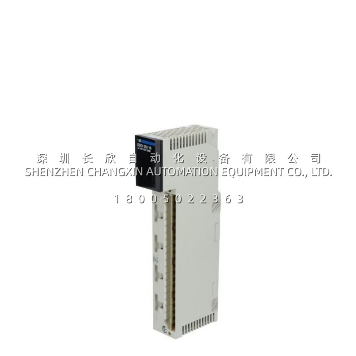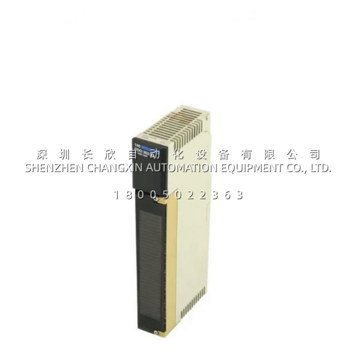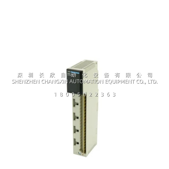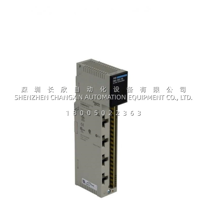
ABB 2REA024239A001​ ACS800 Inverter Control / Interface Board — IGBT Gate-Drive & Signal Conditioning PCB Spare缩略图

ABB 2REA024239A001​ ACS800 Inverter Control / Interface Board — IGBT Gate-Drive & Signal Conditioning PCB Spare

ABB 2REA024239A001​ ACS800 Inverter Control / Interface Board — IGBT Gate-Drive & Signal Conditioning PCB Spare插图


Description

The 2REA024239A001​ is an ABB Inverter Control / Interface Board Assembly (internal drive electronics) designed for use in ABB ACS 600, ACS 800, and selected ACS 350 / ACS 550 inverter drive families. It functions as the signal-conditioning and gate-drive interface between the drive’s main control unit (NDCU / AM33 / Drive Controller) and the inverter-section IGBT power modules. The 2REA024239A001​ distributes PWM firing pulses with optical isolation, monitors DC-link voltage and inverter-phase currents/temperatures, and reports faults (desaturation, over-current, under-voltage on gate-emitter) back to the main CPU. Powered from the drive’s internal 24 V DC auxiliary supply, this conformal-coated PCB plugs into a dedicated backplane slot or interfaces via ribbon / fiber harness to the power stack — it is a non-field-wirable internal spare essential for repairing inverter-stage faults without replacing the entire drive.

h2 Application Scenarios

In a steel rolling mill, a 400 kW ACS 800-04 drive suddenly trips on “Inverter Fault / HW Fault” with no obvious cause in the motor or incoming supply. Detailed diagnostics point to intermittent loss of the gate-driver acknowledge signal from the inverter section. The drive engineer isolates power, removes the inverter compartment cover, and swaps the 2REA024239A001​ board (which is held by two screws and a multi-pin header / ribbon to the IGBT stack). On power-up the fault clears, and a test-run confirms stable operation. Because the board is a direct plug-in spare, the drive is back online in under 15 minutes — avoiding a €15k+ complete inverter replacement and a multi-day lead time. This scenario demonstrates how the 2REA024239A001​ solves the MRO pain point of catastrophic drive write-off due to a single electronics failure, and reduces mean time to repair (MTTR) to a simple board exchange.

h2 Parameter

Main Parameters Value/Description
Product Model 2REA024239A001​ (ABB Drives Internal Spare — Inverter Interface / Control Board)
Manufacturer ABB (ABB Motion — Drives Division, Helsinki / Vaasa Plant)
Product Category Inverter Section Control / Interface PCB Assembly (Gate-Drive & Signal Conditioning Board)
Compatible Drives ABB ACS 600, ACS 800-01 / -04 / -07 / -11 (certain frame sizes); also cross-used in some ACS 350/550 inverter stacks — verify by drive type plate & existing board label
Supply Voltage (Internal) 24 V DC ±15 % (derived from drive auxiliary PSU via backplane / cable)
Primary Function PWM distribution to IGBT gates (opto-isolated), DC-link & phase-current monitoring, temperature feedback, fault reporting to NDCU / AMC
Interface to Power Stage Ribbon / flat-flex / pin-header to IGBT driver daughter-cards or direct to gate-driver optocouplers
Backplane / Comm. to CPU Proprietary serial / parallel link to main control board (NDCU-03 / AM33 etc.)
Onboard Indicators PWR LED, FLT / ACK LEDs (model-dependent)
Protection Features Desat detection, shoot-through prevention logic, under-voltage lockout on gate supply
Coating Conformal coated (humidity & contamination resistant — standard for drive internals)
Operating Temp. (Board) -20 °C to +70 °C (within drive cabinet ambient)
Mounting Secured by M3/M4 screws + keyed header or ribbon to inverter stack


h2 Technical Principles and Innovative Values

  • Innovation Point 1 — Optically Isolated PWM Distribution with Integrated Desaturation Protection:​ The 2REA024239A001​ receives low-voltage PWM commands from the drive CPU and transfers them across high-speed optocouplers to the IGBT gate drivers, providing > 2.5 kV isolation between control and 600–690 V power stages. Built-in VCEdesaturation detection immediately inhibits gate turn-on if an IGBT is shorted, protecting the power module from cascading failure — a safeguard not present in generic interface boards.
  • Innovation Point 2 — Closed-Loop Fault Acknowledgment to Drive Controller:​ Unlike passive distribution boards, the 2REA024239A001​ continuously echoes a “watchdog OK” bit to the main controller. If the board loses its own gate-driver supply or detects an IGBT fault, the acknowledge signal drops and the NDCU triggers a controlled drive trip with a specific fault code — enabling precise root-cause diagnosis rather than a generic “Hardware Fault” alarm.
  • Innovation Point 3 — Drop-In Form Factor with Version-Specific Label Matching:​ ABB assigns the 2REA… index to board revisions that are mechanically and electrically interchangeable within a given drive frame size. The 2REA024239A001​ is keyed and connector-polarized to prevent incorrect insertion. Matching the exact 2REA number to the one removed from the drive avoids firmware/hardware mismatch warnings during power-up — a critical detail in drive repair workflows.ABB 2REA024239A001​ ACS800 Inverter Control / Interface Board — IGBT Gate-Drive & Signal Conditioning PCB Spare插图1
ABB 3HNA021184-001 PPRU 3-Channel Proportional Control Valve Unit with CPU for IRB5400/5500 Spray Robots缩略图

ABB 3HNA021184-001 PPRU 3-Channel Proportional Control Valve Unit with CPU for IRB5400/5500 Spray Robots

ABB 3HNA021184-001 PPRU 3-Channel Proportional Control Valve Unit with CPU for IRB5400/5500 Spray Robots插图


Description

The ABB 3HNA021184-001​ (internal reference 2N2402) is a PPRU (Proportional Pressure Regulating Unit) main control module manufactured by ABB for its robotics painting and dispensing systems. Equipped with an onboard industrial CPU and three independent analog control channels, it manages real-time closed-loop regulation of paint flow, atomization air pressure, and fan pattern width in ABB IRB-series spray robots.

Application Scenarios

In a high-volume automotive body shop running ABB IRB 5400​ and IRB 5500​ painting lines, inconsistent paint film thickness was traced back to a failing PPRU module that could no longer maintain stable proportional valve output. After replacing the faulty unit with a genuine ABB 3HNA021184-001​ PPRU—paired with the companion channel board 3HNA007022-001​ and interface card 3HEA800736-003—the system restored ±0.5% flow stability, eliminated orange-peel defects, and reduced solvent waste by 8%. For maintenance engineers, having a verified spare ABB 3HNA021184-001​ on the shelf means avoiding unplanned line stoppages that can cost thousands per hour in lost throughput.

Parameter

Main Parameters Value/DescriptionProduct Model 3HNA021184-001 (Internal Ref: 2N2402)Manufacturer ABB (ASEA Brown Boveri – Robotics Division)Product Category PPRU – Proportional Pressure Regulating Unit / Process Control ModuleControl Channels 3 Independent Analog Channels (Flow / Atom. Air / Fan Width)Onboard Processor Industrial-grade CPU for PID closed-loop regulation & signal scalingSupply Voltage 24 V DC (sourced from IRC5 controller internal PSU)Signal Interface Multi-pin proprietary ribbon & D-sub to proportional valves / transducersCommunication Bus ABB Internal Robot Bus (linked to Main Computer / DSQC modules)Operating Temp. +5 °C to +55 °C (designed for ventilated control cabinet environment)Mounting Method Cabinet DIN-rail or dedicated bracket with multi-connector backplaneAssociated Parts 3HNA007022-001​ (Channel Expansion), 3HEA800736-003​ (Interface Unit)Net Weight Approx. 6.02 kg

Technical Principles and Innovative Values

  • Innovation Point 1 – Dedicated PID Loop Offloading:​ Unlike generic I/O modules, the ABB 3HNA021184-001​ integrates a local CPU that executes PID control for three proportional valves independently, relieving the main robot controller from real-time analog loop computation and improving overall system determinism.
  • Innovation Point 2 – High-Resolution Analog Conditioning:​ Each of the three channels supports fine-grained 0–10 V / 4–20 mA signal conditioning with built-in dither generation and dead-band compensation, ensuring smooth paint atomization without micro-oscillation in the solenoid drivers.
  • Innovation Point 3 – Seamless Integration with Dispense Pac:​ The ABB 3HNA021184-001​ is natively supported by ABB RobotWare Dispense option, allowing parameter tuning (Kp/Ki/Kd, ramp times, min/max clamp) directly from the FlexPendant without external calibration tools.
  • Innovation Point 4 – Field-Proven Ruggedization:​ Conformal-coated PCB and galvanically isolated I/O stages protect against EMI from nearby servo drives and transient voltage spikes common in paint shop cabinets.


Application Cases and Industry Value

A Tier-1 appliance manufacturer operating four ABB IRB 5500​ painting cells reported chronic first-pass yield issues due to fluctuating bell atomization pressure. Root-cause analysis identified drift in the legacy PPRU unit. The maintenance team retrofitted ABB 3HNA021184-001​ (with matched 3HNA007022-001) and recalibrated via RobotStudio. Post-installation, atomization pressure variance dropped from ±12 kPa to ±2 kPa, first-pass yield improved by 4.2%, and the line has run >18,000 hours without PPRU-related faults. This demonstrates the critical role a properly functioning PPRU plays in coating quality assurance and OEE improvement.

ABB / Fuji 2MBI600VX-120-50: 1200V 600A Dual IGBT Module for ACS / PST Drive Power Stacks缩略图

ABB / Fuji 2MBI600VX-120-50: 1200V 600A Dual IGBT Module for ACS / PST Drive Power Stacks

ABB / Fuji 2MBI600VX-120-50: 1200V 600A Dual IGBT Module for ACS / PST Drive Power Stacks插图


Description

The 2MBI600VX-120-50​ is a 1200 V, 600 A dual (2-pack) IGBT module with anti-parallel free-wheeling diodes, manufactured by Fuji Electric and widely used as the primary power semiconductor in ABB ACS600 / ACS800 / ACS850 drives and PSTB Series soft starters. Housed in a rugged isolated-baseplate package with screw power terminals and press-fit signal pins, it forms the inverter leg of medium-to-high power drive power stacks, converting DC bus voltage into variable-frequency AC for motor control.

Application Scenarios

Consider a cement plant where a 1.2 MW ID fan is driven by an ABB ACS800-104 inverter. After 16 years of continuous duty, one phase of the inverter begins showing unbalanced DC bus ripple and occasional “Overcurrent Phase” trips—classic symptoms of a degrading IGBT in the u-phase leg. Removing the entire drive would require a multi-day shutdown. Instead, during a planned kiln cool-down, the drive technician isolates power, discharges the DC link, removes the clamps / pressure plate, extracts the suspect 2MBI600VX-120-50, and installs a verified replacement (matched VCE(sat)characteristic to remaining legs). After re-torquing the new module’s terminals and reinstalling the clamping plate to spec, the drive powers up, passes the built-in IGBT test, and the fan returns to service—total intervention under 90 minutes. The 2MBI600VX-120-50​ directly solves the legacy-drive spares gap for plants extending the life of proven ABB drive assets, turning a potential drive-change project into a board/switch-level repair.

Parameter

Main Parameters Value/Description
Product Model 2MBI600VX-120-50​ (Alt. Ref: 2MBI600VX120-50, 2MBI600VX-120-50)
Manufacturer Fuji Electric (approved / cross-listed for ABB drive power sections)
Product Category Dual (2-Pack) IGBT Module + Anti-Parallel FWD (Free-Wheeling Diode)
Collector-Emitter Voltage VCES 1200 V
Collector Current IC(Tc=100°C) 600 A
ICPulse (1 ms, Tc=100°C) 1200 A
VCE(sat)typ. @ IC=600A ≈ 2.1–2.4 V (VX series low saturation — verify datasheet rev.)
Gate-Emitter Voltage VGES ±20 V
Isolation Voltage VISO(AC 1 min) 4000 V AC (Baseplate ↔ Terminals)
Switching Frequency (Recommended) ≤ 3 kHz typical for inverter apps; up to 20 kHz possible with derating
Package / Baseplate Standard Fuji 2MBI footprint; AlSiC or Cu-base isolated baseplate (NTC not included on this variant)
Mounting / Connections M8 power screw terminals; press-fit / solder signal pins; clamped via pressure plate to heat sink
Operating Junction Temp. Tj -40 °C to +150 °C (Tj(max)= 150 °C)
Weight (Approx.) 1.6–2.0 kg
Typical ABB Drive Fitment ACS800-04/-07/-104 (frame sizes R8–R11 depending on power), PSTB soft starter thyristor/IGBT stages (selected ratings)


Technical Principles and Innovative Values

  • Innovation Point 1 — V-Series Low-VCE(sat)Chip Technology:​ The 2MBI600VX-120-50​ uses Fuji’s 6th/7th-gen V-Series IGBT chips with optimized carrier lifetime, achieving typical VCE(sat)≈ 2.15 V at 600 A. This reduces conduction losses by 10–15 % vs. older U-Series equivalents, lowering heatsink delta-T and extending drive-component life in high-duty-cycle applications like fans, pumps, and conveyors.
  • Innovation Point 2 — Isolated Baseplate with Low Thermal Resistance:​ The direct-bonded copper (DBC) substrate on an AlSiC/Cu baseplate provides Rth(j-c)≈ 0.065 K/W (typical for IGBT portion), ensuring efficient heat transfer into the drive’s liquid- or forced-air-cooled heatsink. The isolated baseplate (≥ 4 kV AC isolation) eliminates the need for additional insulating mica between module and grounded heatsink—simplifying installation and improving thermal contact.
  • Innovation Point 3 — Drop-In Footprint for ABB Drive Power Stacks:​ The module follows the industry-standard 2MBI 600 A / 1200 V footprint. In ABB ACS800 power sections it drops directly onto the existing heatsink location, uses the same M8 power-terminal torque spec (typically 18–22 N·m), and seats under the original pressure-clamping arrangement—no machining, no adapter plates, no rewiring of the DC-link busbars.


Application Cases and Industry Value

A Middle Eastern petrochemical plant runs ABB ACS800-104 drives on its 50 Hz / 690 V extractor fans. One drive began logging sporadic “Phase U Overcurrent” and “DC Link Unbalanced” faults. Trend data showed gradual rise in IGBT junction-estimated temperature on one leg. The drive was taken out of service during a turnaround; the suspected u-phase 2MBI600VX-120-50​ was removed and a new module static-tested (VCE(sat), gate-emitter leakage, diode VF) before installation.Post-replacement and torque verification per ABB manual, the drive passed the built-in IGBT self-test and was returned to service. The site instrumentation lead commented: “The 2MBI600VX-120-50​ was a perfect form-fit. We kept the original busbars, clamps, and cooling. One module swap saved us a full drive change-out quoted at $45 K. It’s now on our critical-spares list.”The plant deferred a drive-modernization project by an estimated 6–8 years and avoided a multi-day shutdown.

ABB 1VCR007346 G0032 REF542plus HMI Unit — Local Operator Panel with LCD, Keypad & LED Annunciation缩略图

ABB 1VCR007346 G0032 REF542plus HMI Unit — Local Operator Panel with LCD, Keypad & LED Annunciation

ABB 1VCR007346 G0032 REF542plus HMI Unit — Local Operator Panel with LCD, Keypad & LED Annunciation插图


Description

The ABB 1VCR007346 G0032​ is a Local Human Machine Interface (HMI) / Operator Panel Unit designed specifically for the ABB REF542plus integrated protection, control, and monitoring device used in medium-voltage (MV) substations. It features an alphanumeric or graphical LCD display, a navigation keypad for menu browsing, function keys for direct command execution (Open / Close / Reset / Ack), and dedicated alarm / status LEDs — allowing authorized personnel to view measurements, acknowledge alarms, review sequence-of-events (SOE) and disturbance records, and modify protected settings locally without a laptop or SCADA connection.

Application Scenarios

A 33 kV ring-main substation feeding a large industrial complex had its REF542plus-based feeder protection panel installed in a switchroom without permanent SCADA link during early commissioning. The commissioning engineer used the locally mounted ABB 1VCR007346 G0032​ HMI to navigate the REF542plus menu tree: checking VT/CT ratio settings, viewing live phase currents and voltages, acknowledging a pre-alarm on one feeder, and stepping through the disturbance record from a recent in-zone fault test. During a later site visit, a protection technician needed to verify a changed pick-up setting — the 1VCR007346 G0032​ provided direct read/write access via password-protected menu, with the yellow ALARM LED flashing to draw attention to a pending control-power-loss advisory. The site’s senior electrical engineer remarked: “Having the 1VCR007346 G0032​ on the door means we don’t have to drag a laptop and PCM600 dongle just to check a setting or see why an alarm is lit. It’s an essential part of the bay — the ‘face’ of the relay.”

Parameter

Main Parameters Value/Description
Product Model 1VCR007346 G0032​ (REF542plus HMI / Local Operator Interface Unit)
Manufacturer ABB (Power Technologies — REF542plus Series Accessory)
Product Category Local HMI / Operator Panel / Display & Keypad Unit for REF542plus IED
Display Type Monochrome graphic LCD or 4 × 20 alphanumeric LCD (version-dependent; G0032 typically graphic)
Keypad 16–20 keys: Navigation (↑↓←→ / Enter / Esc), Function keys (F1–F4), Cmd (Open/Close/Reset/Ack)
LEDs Power (green), Alarm / Trip (yellow/red), Comms Activity, Run (green)
Interface to Host Proprietary ribbon / flat-flex cable to REF542plus main CPU board (plug-in)
Language Support Multilingual menu (English, German, French, Spanish, Italian, etc. — selectable in REF542plus config)
Beeper / Annunciator Audible key-press & alarm beep (can be muted via menu)
Mounting Front-panel of REF542plus enclosure or flush-mounted in cubicle door (via extension cable / bezel kit)
Operating Temp. -20 °C to +55 °C (-4 °F to +131 °F)
Supply Via REF542plus main unit (5 V DC from backplane)
Dimensions (approx.) 144 × 108 mm (W × H) faceplate; depth ~30 mm behind panel
Cable / Accessories Extension flat-cable and door-mount bezel typically ordered separately (check kit code)
Compatibility REF542plus CPU boards — verify firmware version (some early V1.x vs V2.x may require specific HMI revision)
Standards IEC 60255-21 (Env.), IEC 61850 SCL readable via host IED


Technical Principles and Innovative Values

The ABB 1VCR007346 G0032​ is purpose-built as the local man–machine interface for bay-level protection equipment:

  • Innovation Point 1 — Direct Access to IED Data Without Engineering Tool:​ The HMI communicates with the REF542plus CPU over the internal bus and can display real-time analog measurements, binary status, SOE lists, self-test results, and disturbance waveforms — all password-protected by user level (Operator / Engineer / Admin). This empowers field staff to investigate alarms on the spot, reducing unnecessary call-outs.
  • Innovation Point 2 — Context-Sensitive Function Keys & Command Confirmation:​ The 1VCR007346 G0032​ includes dedicated Open / Close / Reset / Acknowledge keys with a two-step confirmation dialog (“Sure?”) to prevent accidental breaker operation — a critical safety feature in MV switchgear. Function keys (F1–F4) are context-sensitive, changing labels on the LCD per the active menu.
  • Innovation Point 3 — Multi-Language Menu with Runtime Selection:​ The HMI renders menus in the language configured in the REF542plus project file. On-site personnel can switch language via a few keystrokes — valuable for multinational sites or contractors — without reconnecting a PC.
  • Innovation Point 4 — Flush-Door Mounting Option with Extension Cable:​ An optional flat-flex extension cable and door-mounting bezel allow the 1VCR007346 G0032​ to be mounted on the cubicle’s outer door while the REF542plus remains inside the earthed switchgear compartment. This preserves IP rating of the panel and lets operators interact with the relay without opening the HV compartment.
ABB 1VCR000993G0002: Wide-Input 110–230 V AC Power Board with Short-Circuit & Over-Temp Protection缩略图

ABB 1VCR000993G0002: Wide-Input 110–230 V AC Power Board with Short-Circuit & Over-Temp Protection

ABB 1VCR000993G0002: Wide-Input 110–230 V AC Power Board with Short-Circuit & Over-Temp Protection插图


Description:

The ABB 1VCR000993G0002​ is an internal Switch-Mode Power Supply Board / PCB Assembly manufactured by ABB, commonly deployed inside ABB medium-voltage drive door units (INU cabinets), control cubicles, or as an auxiliary PSU in DCS/relay subracks. It converts a wide-range AC mains input (typically 88–264 V AC) into regulated low-voltage DC outputs—most commonly 24 V DC for control logic and 5 V DC / ±12 V DC for internal electronics—with galvanic isolation between primary and secondary sides to protect sensitive measurement and communication circuits from mains-borne transients.

Application Scenarios:

Consider a steel plant’s coiler drive where the ABB medium-voltage inverter’s door-mounted control section houses the AAR01 adapter board, A3 logic supply, and local I/O—all powered by a single ABB 1VCR000993G0002​ power supply board. After 15 years of service, the original board’s electrolytic capacitors began drying out, causing intermittent 24 V DC sag that led to spurious “Loss of Adapter Board” alarms during high-load periods. The maintenance team sourced a direct-replacement 1VCR000993G0002, powered down the door auxiliary disconnect, unplugged the AC input and DC output headers, swapped the board, and re-energized. The new unit accepted the existing 230 V AC station supply unchanged, delivered clean 24 V DC to the control electronics, and the intermittent alarm disappeared immediately—saving a potential forced outage on a critical rolling line. The module’s compact PCB form factor and chassis-mount holes allowed installation in under 10 minutes with zero rewiring of the field-side DC distribution.

Parameter:

Main Parameters Value/Description
Product Model 1VCR000993G0002
Manufacturer ABB (ABB Drives / Power Systems Division)
Product Category Internal Switch-Mode Power Supply Board / PCB Assembly (PSU)
Typical Application ABB MV Drive INU Door Electronics, DCS/Relay Subrack Aux Power, Control Cubicle DC Distribution
Input Voltage 88 – 264 V AC (auto-ranging), 47–63 Hz; some variants accept 110–250 V DC
Output Voltage(s) Primary: 24 V DC regulated; Secondary: 5 V DC and/or ±12 V DC (per load requirement of host system)
Rated Output Current 24 V DC @ approx. 5 A (120 W typical; exact total depends on auxiliary rail loading)
Efficiency ≥ 85–88 % typical at full load
Isolation Voltage Input–Output ≥ 1500 V AC (galvanic isolation per IEC 60950 / IEC 60664)
Protection Features Short-circuit, overload (hiccup mode), over-temperature, in-rush current limiting
Status Indication Onboard LED (green = output OK; off or red = fault / no AC input)
Cooling / Enclosure Natural convection (fanless); open-frame PCB with metal mounting flanges / standoffs
Mounting Method Chassis mount via M3/M4 screw holes or guide-slot in designated PSU location inside enclosure
Operating Temperature –10 °C to +60 °C (derating above 50 °C typical); storage –40 °C to +85 °C
Dimensions (approx.) 130 × 90 × 35 mm (L × W × H), Weight ≈ 0.30–0.45 kg
Certifications CE, UL / cULus (per system certification), RoHS-compliant


Technical Principles and Innovative Values:

  • Innovation Point 1: Universal Auto-Ranging AC Input with Active PFC.​ The ABB 1VCR000993G0002​ accepts worldwide mains voltages (88–264 V AC) without a voltage selector switch, making it suitable for multinational projects and plants with uncertain supply specifications. Active Power Factor Correction reduces input harmonic current draw versus linear transformers.
  • Innovation Point 2: Multi-Rail DC Generation with Tight Regulation.​ Rather than providing only 24 V DC, the board typically generates and stabilizes multiple internal voltage rails (5 V for logic, ±12 V for analog/I/O where required), ensuring the downstream adapter boards, gate-pulse amps, and communication cards receive clean, ripple-free power—critical for accurate A/D conversion and noise-free fiber-optic signaling.
  • Innovation Point 3: Galvanic Isolation & Hiccup-Mode Overload Recovery.​ The primary–secondary isolation barrier protects sensitive control electronics from mains transients and ground loops. In an overload condition the 1VCR000993G0002​ enters “hiccup” mode (cycling off/on) rather than latching off permanently; once the fault clears, it auto-recovers—reducing the need for manual reset visits during nuisance trips.
ABB 1TNE968900R1210 (Type PM564-R A0): Expandable Eco Series Central Processing Unit, 128 kB Mem缩略图

ABB 1TNE968900R1210 (Type PM564-R A0): Expandable Eco Series Central Processing Unit, 128 kB Mem

ABB 1TNE968900R1210 (Type PM564-R A0): Expandable Eco Series Central Processing Unit, 128 kB Mem插图

Description:

The 1TNE968900R1210, type-designated PM564-R A0, is an ABB Eco series Programmable Logic Controller (PLC) Central Processing Unit (CPU) module. It is a compact, standalone controller with an integrated 24 V DC power supply input, eight 24 V DC digital inputs, and six built-in relay outputs (SPDT / Form C), designed for small-scale machine control, building automation, and OEM equipment applications. The PM564-R A0 executes IEC 61131-3 compliant programs, supports Modbus RTU master/slave communication via its serial port, and is expandable with ABB Eco local I/O modules to accommodate growing I/O requirements.h2 Application Scenarios:A regional bottled-water contract packer was relying on a discontinued mini-PLC to sequence a 3-station case erector, glue applicator, and outfeed conveyor. The original controller failed and replacement parts were unavailable. The integrator specified the 1TNE968900R1210 (PM564-R A0)​ as a direct functional replacement. The eight onboard DI points accepted dry-contact signals from photoeyes and limit switches; the six onboard relay outputs (NO/NC) directly switched the 24 V DC solenoid valves and a small 120 V AC stack-light beacon—no intermediate interposing relays needed thanks to the SPDT relay rating. Using ABB PS501 programming software (IEC 61131-3), the original ladder logic was recreated in one afternoon. On startup, the built-in Modbus RTU port allowed the packer’s main line HMI to poll the machine status word. The project came in under budget and the packer resumed full-rate production the same day. The OEM service manager noted that the PM564-R A0​ “gave us more I/O flexibility and better diagnostics than the original, in the same DIN-rail footprint.”h2


Parameter:

Main Parameters Value/Description
Product Model 1TNE968900R1210​ (Type PM564-R A0)
Manufacturer ABB
Product Category Eco Series Programmable Logic Controller — CPU Module with Built-In I/O
Onboard Digital Inputs 8 × 24 V DC (sink/source), 4.5–30 V DC range, typ. 3 mA @ 24 V DC
Onboard Digital Outputs 6 × Relay (SPDT / Form C), 2 A @ 250 V AC / 30 V DC (resistive load)
Program Memory 128 kB (typical for PM560/PM564 Eco CPUs)
Data / Retentive Memory Battery-backed retentive flags & timers (supercapacitor or optional battery backup)
Execution Time ≈ 0.5–1 ms per 1K instructions (bit logic)
Communication Port 1 × RS-485 (Modbus RTU Master / Slave, ASCII mode also supported)
Expansion Capability Up to 3–7 local Eco I/O expansion modules (digital / analog / temperature) depending on bus load
Supply Voltage 24 V DC (18–30 V DC), typ. power consumption ≤ 5 W
Programming Standard IEC 61131-3 (LD, FBD, IL, ST, SFC) via ABB PS501 / Automation Builder
Status Indication PWR, RUN, ERR LEDs + per-I/O status LEDs on front panel
Operating Temperature 0 °C to +55 °C
Mounting Method 35 mm DIN rail (TS35) — width approx. 72 mm (4 TE)
Certifications CE, cULus, RoHS, compliant with IEC 61131-2
Key Note “R” suffix = Relay output version; “T” suffix = Transistor (NPN) output version also available (PM564-T)

h2 Technical Principles and Innovative Values:

  • Innovation Point 1 — All-in-One Compact Design with True Relay Outputs.​ The 1TNE968900R1210​ integrates CPU, power, 8 DI and 6 relay DO in a single 72 mm wide module, eliminating the need for a separate base rack or interposing relays for small machines. The SPDT relay contacts can switch AC or DC loads directly—useful for driving small contactors, indicator beacons, or solenoid valves without additional hardware, reducing panel space and wiring complexity.
  • Innovation Point 2 — IEC 61131-3Programming with Built-In Modbus RTU.​ Unlike proprietary “smart-relay” type controllers, the PM564-R A0 is programmed in standard languages (Ladder, FBD, ST) using ABB PS501 / Automation Builder, and natively supports Modbus RTU on the onboard RS-485 port. This allows the 1TNE968900R1210​ to act as a slave to a plant-wide SCADA/MES or as a master polling remote temperature/flow transmitters—bringing small-machine data into the enterprise network without a protocol gateway.
  • Innovation Point 3 — Expandable Architecture Protecting OEM Investment.​ The Eco bus allows snap-on local expansion modules (additional DI/DO, AI/AO 0–10 V / 4–20 mA, thermocouple/RTD, high-speed counter) to be added as application needs grow. An OEM specifying the PM564-R A0​ today can double I/O count later without changing the CPU or rewriting the base program—future-proofing the control architecture for machine model variations.
ABB 1TGE120026R0103: Industrial Touch Screen Display for Process Control & Machine Visualization缩略图

ABB 1TGE120026R0103: Industrial Touch Screen Display for Process Control & Machine Visualization

ABB 1TGE120026R0103: Industrial Touch Screen Display for Process Control & Machine Visualization插图


Description:

The ABB 1TGE120026R0103​ is an industrial Touch Screen Panel / Human Machine Interface (HMI) display unit, belonging to ABB’s CP400 / Panel 800 family (commonly associated with the PP820 / PP826 form factor). It features a 10.4-inch TFT color LCD with resistive touch overlay and communicates with ABB AC800M, AC800xA, Freelance, or AC500 PLCs via Ethernet (TCP/IP, Modbus TCP) or serial (RS-232/485) links. The 1TGE120026R0103​ provides real-time process visualization, alarm acknowledgment, trend viewing, and parameter adjustment directly at the machine or control-room local station, enclosed in a NEMA4X / IP65 front-rated bezel for wash-down and harsh-plant environments.

Application Scenarios:

Picture a continuous-digestion pharmaceutical batch plant where the local 10.4″ HMI beside the reactor skid begins showing flickering backlight and unresponsive touch areas—operators can no longer reliably acknowledge high-priority alarms during the night shift. The panel is an ABB 1TGE120026R0103​ integrated into the Freelance 2019 control system. During a scheduled 20-minute process hold, the technician disconnects the 24 V DC supply and the RJ45 + serial cables, releases the four panel-mount clamps from behind the cutout, and slides the old unit out. A new 1TGE120026R0103​ is inserted, cables reconnected, and the panel boots—automatically loading the application project pre-downloaded from the engineering station or restored from the panel’s onboard memory. Within seconds the process overview appears, touch responds crisply across all quadrants, and the alarm bell is silenced via the touchscreen. Because the 1TGE120026R0103​ is a direct mechanical and electrical replacement, no cutout modification or re-wiring is required—the line is back under local visual control in minutes, averting a potential batch abort. The key pain point solved: a drop-in HMI replacement that restores operator situational awareness and alarm-handling capability without re-engineering the control network or re-cutting the panel.

Parameter:

Main Parameters Value/Description
Product Model 1TGE120026R0103​ (ABB Panel 800 / CP400 family – 10.4″ TFT Touch Version)
Manufacturer ABB (Sweden / Switzerland)
Product Category Industrial Touch Screen HMI Panel / Operator Interface Terminal
Display Type 10.4″ TFT Color LCD, 64K colors (18-bit), SVGA 800 × 600 pixels
Touch Screen Analog Resistive (5-wire), operable with finger or stylus; > 1 million touches life
Processor / Memory Onboard RISC CPU + Flash / DRAM (project storage & runtime; typical 128–256 MB Flash, 64–128 MB RAM per platform generation)
Interfaces / Ports 1 × 10/100 Mbps Ethernet (RJ45), 1–2 × serial (RS-232 / RS-485 configurable), USB (for project download / mouse / printer on some revisions)
Supported Protocols ABB Control Builder / 800xA Faceplate Protocol, Modbus TCP/RTU, OPC (via connected controller), IEC 60870-5-104 (via gateway)
Supply Voltage 24 V DC ±20 % (18–30 V DC), typical consumption 15–25 W
Front Protection IP65 / NEMA 4X (front face); rear IP20 – for panel-mount indoor use
Operating Temp. 0 °C to +50 °C (storage: -20 °C to +60 °C); 5–95 % RH non-condensing
Mounting Panel cutout mount (approx. 266 × 210 mm cutout for 10.4″ version) with clamp brackets
Certifications CE, UL 508 / cULus, FCC Part 15 Class A, RoHS


Technical Principles and Innovative Values:

The 1TGE120026R0103​ is a dedicated process-visualization terminal, not a general-purpose monitor. It runs the ABB Panel Builder 800 application runtime and synchronizes tightly with ABB controller tag databases.

  • Innovation Point 1: Native Tag Synchronization with ABB 800xA / Freelance Controllers.​ When connected to an AC800M or Freelance CPU, the 1TGE120026R0103​ can import the controller’s variable list directly into Panel Builder 800. This eliminates duplicate tag definition, reduces configuration errors, and ensures faceplate symbols reflect real-time process states (quality, simulation mode, forced values) consistently with the control-room DCS graphics.
  • Innovation Point 2: Resistive Touch Optimized for Industrial Glove & Wet Conditions.​ Unlike capacitive screens that fail with gloved operators or moisture, the 5-wire resistive overlay on the 1TGE120026R0103​ works reliably with latex gloves, through light condensation, and with a stylus—essential in food, pharma, and outdoor-utility HMI locations. The touch controller includes auto-calibration and drift compensation to maintain accuracy over temperature swings.
  • Innovation Point 3: Project Portability & Local Data Buffering.​ The 1TGE120026R0103​ stores the full HMI project (graphics, alarms, trends, recipes) in onboard non-volatile memory and can buffer alarm/event lists locally during brief controller or network interruptions. On reconnection, events are time-stamped and forwarded. This allows the panel to function as a stand-alone annunciator and data viewer even when the SCADA server is temporarily offline—a critical resilience feature in batch and continuous processes.


Application Cases and Industry Value:

  • Case 1 – Dairy Spray-Dryer Local HMI Replacement (Western Europe):​ A food plant’s original 10.4″ HMI on the spray dryer began exhibiting dead touch zones after 9 years. The integrator replaced it with a 1TGE120026R0103, reloaded the Panel Builder project from backup, and the dryer was back online in 12 minutes. Operators reported improved brightness and contrast vs. the aged original. The plant standardized the 1TGE120026R0103​ across five dryer lines to simplify spares holding—one HMI type fits all local stations.
  • Case 2 – Water-Treatment Pump Station Remote HMI (Asia-Pacific):​ A municipality installed the 1TGE120026R0103​ in a NEMA 4X stainless-steel wash-down enclosure at a remote borehole pump station, connected via a serial RS-485 link to the local AC500 PLC. The panel displays real-time pump run-status, VFD speed, and high-level alarms, and allows authorized staff to manually start/stop pumps during SCADA-link maintenance. The resistive touch performed reliably in the humid tropical environment, and the panel survived a minor insect-ingress event without failure—leading the utility to adopt it as standard for 20+ remote stations.
ABB 1TGE102009R1001 Interface Module – CS31 / Profibus DP Slave Communication Card for AC31 PLC缩略图

ABB 1TGE102009R1001 Interface Module – CS31 / Profibus DP Slave Communication Card for AC31 PLC

ABB 1TGE102009R1001 Interface Module – CS31 / Profibus DP Slave Communication Card for AC31 PLC插图 ABB 1TGE102009R1001 Interface Module – CS31 / Profibus DP Slave Communication Card for AC31 PLC插图1

Description

The ABB 1TGE102009R1001​ is a system interface / communication module—commercially referenced as the XD16L1​ (low-profile) or XD16H1​ (high-feature) variant—designed for insertion into the local expansion bus of ABB AC31 series programmable logic controllers (CPU-50, CPU-90, CPU-200, CPU-400). Its primary function is to serve as the CS31 bus master or slave interface, converting the AC31’s internal parallel bus protocol into the serial CS31 fieldbus standard (RS-485 based, galvanically isolated) for communication with remote I/O stations, text displays, or peer AC31 CPUs. It is a cornerstone component for building distributed control architectures around the proven AC31 platform.h2 Application ScenariosPicture a cement plant where the main kiln is controlled by an ABB AC31-200 CPU with local XC08L1 I/O, while three remote crushing/sieving stations 200–400 meters away are equipped with CS31-based remote I/O drops (e.g., CS31-DI32, CS31-DO16, CS31-AI08). The original CS31 interface card in the CPU rack fails after 18 years—the remote I/O stations drop off the network, halting material feed. Rather than re-cabling or migrating to a new DCS, the maintenance team sources a functionally tested ABB 1TGE102009R1001. They power down the CPU rack, extract the faulty module from the local-bus slot, insert the replacement, and reconnect the shielded twisted-pair CS31 bus (A/B/+SHLD). On power-up the module’s RUN LED illuminates, the CS31 network reinitializes automatically using the stored bus parameters (baud rate 187.5 kbps, station addresses already configured in the PLC program), and all three remote stations resume data exchange within seconds. This scenario highlights the 1TGE102009R1001‘s essential role: it is the single point of CS31 connectivity that ties distributed I/O into the AC31 control core—replacing it quickly restores full plant communication with zero reprogramming.h2


Parameter

Main Parameters Value/Description
Product Model 1TGE102009R1001
ABB Type Designation XD16L1 / XD16H1 (verify by removed unit label)
Manufacturer ABB (Industrial IT / AC31 Series)
Product Category AC31 Local Bus Interface / CS31 Communication Module
Compatible Host ABB AC31 CPUs — CPU-50, CPU-90, CPU-200, CPU-400 (mounts on CPU local-bus expansion slot or dedicated interface slot)
Fieldbus Supported ABB CS31 (serial, RS-485 based, half-duplex)
Transmission Rate 187.5 kbit/s (fixed CS31 standard)
Max. Nodes (CS31 Network) Up to 32 stations (1 Master + 31 Slaves)
Max. Cable Length 500 m (with repeater extendable; proper shielding required)
Isolation Galvanic isolation ≥ 500 V between CS31 line & internal logic
Connector Screw terminals for CS31 A/B/SHLD + flat-cable to AC31 local bus
Indicators PWR (power), RUN (CS31 active), ERR (fault/collision)
Bus Supply From AC31 CPU / local-bus backplane (24 V DC internally regulated)
Operating Temperature 0 °C to +55 °C (IEC 61131-2)
Mounting Plugs into AC31 CPU local-bus slot or dedicated interface slot on CPU housing
Dimensions (H×W×D) ≈ 90 × 72 × 60 mm (compact AC31 module format)
Weight ≈ 0.15 kg

*Note: Some AC31 systems use the XC548 / XB348 as alternative bus couplers for Profibus DP — the 1TGE102009R1001 is CS31-specific. Always match the exact alphanumeric suffix (XD16L1 vs XD16H1) with the original removed module.h2 Technical Principles and Innovative ValuesThe 1TGE102009R1001​ implements the CS31 master/slave protocol in dedicated ASIC/firmware, offloading cyclic data exchange from the AC31 CPU.

  • Innovation Point 1 – True Plug-and-Play CS31 Master: The 1TGE102009R1001​ auto-manages CS31 token-passing and cyclic I/O image swapping. Once the PLC program defines the remote I/O map (via PG2000 or Automation Builder), the module transparently handles frame assembly, CRC checking, retry on timeout, and status reporting—freeing the CPU for control logic execution and ensuring deterministic scan-time regardless of CS31 traffic.
  • Innovation Point 2 – Galvanically Isolated RS-485 with Surge Protection: The CS31 physical layer on the 1TGE102009R1001​ features optical isolation and line-protection components capable of withstanding typical industrial transients (ESD, induced surge from switching heavy loads). This breaks ground loops between the control cabinet and remote I/O locations spread across a plant, a common cause of communication instability in electrically noisy environments like mines or steel mills.
  • Innovation Point 3 – Transparent Swap Preserves Network Configuration: All CS31 parameters (master/slave mode, station addresses of slaves, I/O mapping) reside in the AC31 CPU’s application memory—not on the interface card. Swapping a faulty 1TGE102009R1001​ requires no re-addressing or re-download; the replacement is recognized on power-up and resumes bus master/slave operation using the stored configuration, minimizing MTTR during unplanned outages.
ABB 1TGE120010R1000 MControl Board – 24V DC Control & Interface PCB for Drive & Automation Systems缩略图

ABB 1TGE120010R1000 MControl Board – 24V DC Control & Interface PCB for Drive & Automation Systems

ABB 1TGE120010R1000 MControl Board – 24V DC Control & Interface PCB for Drive & Automation Systems插图


Description:

The ABB 1TGE120010R1000​ is an MControl / MicroControl interface board (also referenced in catalogs as an MCM-MC type control PCB) operating on 24 V DC, designed for integration into ABB drive cabinets (ACS600/ACS800 series option slots or control compartments) and ABB MControl-based process automation panels. It provides local digital I/O scanning, serial communication (typically RS-485), and acts as a bridge between the drive/machine controller and external operator devices, marshalling panels, or a supervisory PLC — making it a critical interface element in legacy ABB automation architectures.

Application Scenarios:

A steel processing plant running an ABB ACS800-based main drive on its pickling line suddenly lost all local “Jog Forward / Jog Reverse” pushbutton control and the associated “Drive Ready” lamp on the machine-side pendant. The drive itself communicated fine with the plant DCS via Profibus, but the local hard-wired controls were dead. Diagnostics pointed to failure of the internal ABB 1TGE120010R1000​ MControl board — the small 24 V DC interface PCB that scans the pendant’s pushbutton matrix and drives the status LEDs. The electrician powered down the drive cabinet, extracted the faulty board from its guide rails / screw mounts, inserted a verified replacement 1TGE120010R1000, reconnected the 24 V DC supply and the multi-pin ribbon to the pendant, and restored power. Within minutes local jog and lamp functions were back online — no parameter changes, no drive firmware reload. This real-world case shows the 1TGE120010R1000‘s role as the “local human-interface translator” inside ABB drive and MControl panels, and why a tested spare on the shelf can save hours of unplanned downtime.

Parameter:

Main Parameters Value/Description
Product Model 1TGE120010R1000​ (MControl / MicroControl Interface Board, MCM-MC type reference)
Manufacturer ABB
Product Category Control / Interface Circuit Board (MControl PCB, 24 V DC powered)
Compatible System ABB ACS600 / ACS800 Drive Cabinets (option compartment), ABB MControl Panels, PDP612 Nodes, select Advant OCS extensions
Supply Voltage 24 V DC (typical range 18 – 30 V DC)
Power Consumption < 5 W typical
Digital I/O (typical) Configurable — often 8–16 DI + 8–16 DO (depends on host system firmware; some variants DI-only or DO-only)
Communication Interface RS-485 Serial (proprietary MControl / DDCS-like framing) + optional parallel bus to host CPU
Isolation Optical isolation on I/O channels (typical ≥ 1500 V AC)
Status Indication Power LED + Run / Comm LEDs; some channel LEDs per revision
Operating Temperature -20 °C to +60 °C
Storage Temperature -40 °C to +85 °C
Mounting Method Screw-fastened or card-guide insertion with backplane / ribbon cable to host
Protection Class IP20 (for enclosed cabinet installation)
Board Material Industrial-grade FR-4, multi-layer with soldermask & silkscreen
Dimensions (approx.) 180 × 120 × 25 mm (varies slightly by revision/enclosure)
Weight (approx.) 0.20 – 0.30 kg


Technical Principles and Innovative Values:

  • Innovation Point 1 — Local Button-Matrix Scanning with Debounce & LED Drive.​ The ABB 1TGE120010R1000​ continuously scans a connected pushbutton/selector-switch matrix (e.g. on an operator pendant or door-mounted fascia), applies hardware/software debounce, and reports state changes to the host drive or controller via its serial bus. Simultaneously it receives LED-status words from the controller to drive local panel indicators — keeping operator feedback perfectly synchronized with control logic.
  • Innovation Point 2 — 24 V DC Operation with Galvanic I/O Isolation.​ Powered from the same 24 V DC supply that feeds the drive’s control electronics, the 1TGE120010R1000​ uses opto-isolated input stages and buffered output drivers. This prevents ground-loop currents and protects the sensitive host CPU bus from inductive kickback on the field-side wiring — a frequent failure mode in unprotected pendant or panel interfaces.
  • Innovation Point 3 — Plug-and-Play Replacement with No Code Download.​ Because I/O mapping and communication parameters reside in the host controller’s application, the ABB 1TGE120010R1000​ requires no configuration tool or firmware load. Swapping a failed board for a same-part-number unit (verify revision suffix matches) immediately restores function — a true “remove–insert–go” spare part that minimizes MTTR in round-the-clock operations.
Protect PLC Outputs with ABB 1SVR011714R1100 CR-M2SF22 2-Changeover Relay Interface Module缩略图

Protect PLC Outputs with ABB 1SVR011714R1100 CR-M2SF22 2-Changeover Relay Interface Module

Protect PLC Outputs with ABB 1SVR011714R1100 CR-M2SF22 2-Changeover Relay Interface Module插图

Description:

The ABB 1SVR011714R1100, commercially designated as the CR-M2SF22, is a plug-in electromechanical interface relay module belonging to ABB’s CR-M Series of control relays. It features a 24 V DC coil, two changeover (2 CO / DPDT) silver-alloy contacts rated up to 6 A at 250 V AC, an integrated LED status indicator, a manual test/force button, and a built-in RC coil suppression circuit. Designed to be plugged into a matching CR-M socket (typically 90° or straight orientation), the 1SVR011714R1100​ is the industry-standard solution for buffering low-power PLC/DCS digital outputs, driving higher-current loads (pilot lamps, solenoid valves, small contactors), and providing galvanic isolation between sensitive control electronics and noisy field circuits.h2 Application Scenarios:A food-processing plant’s packaging line had its ABB AC500 PLC digital output cards failing prematurely — the root cause was traced to inductive voltage spikes fed back from dozens of 24 V DC solenoid valves directly driven by the DO modules. The panel builder inserted a bank of ABB 1SVR011714R1100​ relay modules between the PLC DO cards and the valve terminals, using the PLC’s 24 V DC DO to energize the relay coil and the relay contacts to switch the valve solenoids. The 1SVR011714R1100​ provided both galvanic isolation and coil-suppression (via its built-in RC snubber), eliminating back-EMF damage to the PLC. The LED indicator also let technicians instantly see which valve was being commanded — something they lost with solid-state interposing. This scenario illustrates the core value of the 1SVR011714R1100: it is the first line of defense for expensive electronic I/O, simplifies troubleshooting with visual status, and standardizes interposing relay wiring across the panel.h2


Parameter:

Main Parameters Value/Description
Product Model 1SVR011714R1100​ (CR-M2SF22)
Manufacturer ABB (ABB Control Products / Low Voltage Division)
Product Category Electromechanical Interface Relay Module / Plug-In Relay
Coil Voltage 24 V DC (Typical tolerance -20% / +25%)
Contact Configuration 2 CO (DPDT / 2 Changeover) — 2 Form C
Contact Rating 6 A @ 250 V AC / 30 V DC (resistive load)
Mechanical Life ≥ 10 million operations
Electrical Life ≥ 100,000 operations @ rated resistive load
Built-In Features LED coil-status indicator + Manual test/force button + RC coil suppression
Socket / Base Type CR-M…S (e.g., CR-M2S / CR-M4S 90° or straight — order separately)
Mounting Method Plugs into DIN-rail mounted CR-M socket (35 mm top-hat rail)
Operating Temp. -40 °C to +70 °C
Protection Rating IP20 (finger-safe when plugged into socket, installed in cabinet)
Certifications CE, UL, CSA, GL (Marine), RoHS


h2 Technical Principles and Innovative Values:

  • PLC I/O Buffering & Galvanic Isolation:​ The 1SVR011714R1100​ decouples the low-current semiconductor outputs of a PLC/DCS (typically 0.5 A max) from the higher inrush or inductive load currents of field actuators. By switching the load through its silver-cadmium-oxide contacts rather than the PLC transistor, it protects the automation hardware from overcurrent, back-EMF, and ground-loop issues — substantially extending I/O module life.
  • Built-In Diagnostics & Test Facility:​ Unlike bare solid-state interposing, the ABB 1SVR011714R1100​ has a front-mounted mechanical test button that can latch the contacts ON for wiring verification without a live PLC signal, plus a bright LED that confirms coil energization at a glance — invaluable during commissioning and fault-finding on live panels.
  • Integrated Coil Suppression for Clean Switching:​ The onboard RC snubber across the 24 V DC coil absorbs the voltage spike generated when the coil is de-energized, preventing EMI from propagating back onto the 24 V DC control bus and reducing false triggering of adjacent sensitive electronics — a frequent problem with unsuppressed relay coils in dense MCCs.
Back to Top

Search For Products

Product has been added to your cart